A Static Balancing Method for Variable Payloads by Combination of a Counterweight and Spring and Its Application as a Surgical Platform

1
Department of Intelligent Robot Engineering, Hanyang University, 222, Wangsimni-ro, Seongdong-gu, Seoul 04763, Korea
2
Department of Industry-University Cooperation Foundation, Hanyang University ERICA, 55 Hanyangdaehak-ro, Sangnok-gu, Ansan, Gyeonggi-do 15588, Korea
3
Department of Electrical and Electronic Engineering, Hanyang University, 55 Hanyangdaehak-ro, Sangnok-gu, Ansan, Gyeonggi-do 15588, Korea
*
Author to whom correspondence should be addressed.
Appl. Sci. 2019, 9(19), 3955; https://doi.org/10.3390/app9193955
Submission received: 13 August 2019
/
Revised: 11 September 2019
/
Accepted: 16 September 2019
/
Published: 20 September 2019
(This article belongs to the Special Issue Next-Generation Surgical Robotics)
Abstract
:Featured Application
Gravity compensation mechanism can be applied to general surgery for which the human fatigue due to long operation time should be minimized.
Abstract
Stackable mechanism architecture has demonstrated effective gravity-balancing over entire workspaces. Adjustable balancing is required when balancing is broken due to changing the payload at the distal end of a mechanism. In this paper, adjustable balancing of the stackable mechanism for a variable payload is investigated. For this, balancing conditions for three adjustable balancing methods are suggested, and a new balancing method combining a spring and counterweight is considered as an effective means of adjustable balancing for variable payloads. The excellent performance of the system is proven through experiments. Electromyography (EMG) sensors are employed to measure the amount of energy expenditure during the drilling task. It was verified through several tests that an operator holding a drill mounted at the distal end of a stackable arm felt less energy compared to an operator holding the drill directly in free space. The developed balancing arm was successfully applied during a mastoidectomy. A 3-step warning algorithm along with a braking function was found to be effective for safe surgery.
1. Introduction
Balancing mechanisms compensating for a gravity load play an important role in mechanical design in terms of energy efficiency. In an active device, gravity balancing helps to minimize the driving torque, thereby increasing the efficiency of the system. In a passive device, the user can use the equipment without feeling the gravity load. Currently, gravity balancing mechanisms are widely applied in industrial, service, and medical robots, as well as in construction.
Research on gravity compensation has been actively carried out, and various applications using gravity compensation have been introduced. Two approaches can be used to design a gravity balancing mechanism, namely a counterweight or a counter spring. Gravity compensation using a counterweight is a method of balancing a mechanism by putting weights on the opposite side of the center of rotation. The gravity compensation method using a spring is a method where the mechanism is balanced using the restoring force of a spring instead of a counterweight. Mahalingam and Sharan discussed the advantages and disadvantages of these two methods [1]. Using counterweights to balance a two degrees of freedom (2-DOF) parallel robot for antennas was suggested by Dunlop and Johns [2]. Streit and Shin [3] proposed a general approach for the equilibration of planar linkages using springs. Gravity balancing of a six degrees of freedom (6-DOF) spatial parallel mechanism by springs was presented by Ebert-Uphoff et al. [4]. Gosselin et al. [5,6,7,8] obtained the gravity balancing conditions of a three degrees of freedom (3-DOF) planar mechanism, 3-DOF spatial parallel mechanism, four degrees of freedom (4-DOF) spatial parallel mechanism, and a 6-DOF parallel mechanism by using both counterweights and springs. Using counterweights and a pantograph, Russo et al. [9] obtained the static balancing conditions of hexapods. Merriam and Howell [10] proposed a general method for statically balanced rotational flexure using an idealized hinge and torsion spring. To obtain the balance of a DELTA parallel robot, three zero-free-length elastic systems (springs) for each connecting kinematic chain were proposed by Simionescu et al. [11]. Liu et al. [12] designed a spatial 6-DOF decoupling parallel mechanism with static balancing using a counterweight and a spring. Kim and Cho [13] proposed a static balancing mechanism for a face robot that uses a gravity compensator (spring). Using the concept of constant potential energy, Kang et al. [14] proposed a statically balanced stackable planar mechanism.
Gravity compensation methods are currently applied to various mechanism designs. A gravity-balancing mechanism design with auxiliary parallelograms was investigated by Agrawal et al. [15]. Agrawal and Fattah [16] also used auxiliary parallelograms to design a reactionless 3-DOF planar parallel mechanism. Briot et al. [17] designed a statically balanced and partial decoupled PAMINSA by adding counterweights at some axes of the pantograph linkages. In the design of a haptic mechanism, Tahmasebi et al. [18] designed a five-bar parallel mechanism by using an actuator as a counterweight. In the design of a service robot, Kim and Song [19] designed a novel multi-DOF gravity balancing robot arm by attaching compression springs at each joint. Employing double parallelograms made it possible to counterbalance a multi-DOF robot arm through the use of springs, and their practical design was also very compact.
The need for a gravity balancing mechanisms for medical devices is growing to support the needs of the medical operator, such as feeling less physical fatigue. The medical microscope being used in operation rooms is such an example. Nakamura et al. [20] designed a medical tool holding arm apparatus that was capable of widely changing the position and angle of a medical tool. Nakamura et al. [21] also designed a gravity balancing medical stand apparatus with a balancing adjustment in accordance with weight changes on the operating side. Moreover, a balancing support mechanism for a medical optical device with a balancing adjustment that can be automatically performed was designed by Nakamura et al. [22]. Nakamura [23] also designed a balancing chair for a medical apparatus. Lessard et al. [24] designed a medical robot for arterial ultrasound examination with partial gravity balancing and optimization based on the addition of torsion springs assembled in a five-bar mechanism. In the design of rehabilitation devices, Banala and Agrawal [25] designed a gravity balancing leg for rehabilitation with a combination of parallelograms and springs. Herder et al. [26] designed a mobile arm support for patients with muscular weakness by using extension springs. Chen et al. [27] designed a spring-loaded exoskeleton for strengthening upper limb muscle groups while preventing overextension injuries. Ciupitu et al. [28] proposed a medical static balancing rehabilitation device using a torsion spiral spring and cylindrical helical spring for supporting weights that are hung from a ceiling. Lessard et al. [29] developed a static balancing parallel robot for medical 3D ultrasound using counterweights and torsional springs on actuated and passive revolute joints. Dillon et al. [30] designed a milling device as an otology surgery robot. They produced patient-specific plans, optimizing the velocity and incidence angles for spherical cutting burrs using image-based density. Dillona et al. [31] also proposed a 4-DOF robot mounted on a patient’s skull. The accuracy of the entire system (image processing, planning, and robot) was evaluated at critical locations.
Researchers have used a number of approaches to deal with the static balancing problem. Seo et al. [32] interpreted the static balancing problem as having open-loop stability under static equilibrium. Preliminary analysis of open-loop stability was conducted for a 3-DOF translational parallel mechanism. The stiffness model of the balancing mechanism was found as the measure of the open-loop stability, and zero stiffness ensured static balancing over the entire workspace of the mechanism. Seo et al. [33] described balancing methods for a passive surgical robot, and Kang et al. [14] also did so for a parallel robot that was designed on the basis of a stackable parallel mechanism. Balancing equations for the stackable mechanism were suggested that ensured gravity compensation in the entire workspace of the mechanism.
The variable payload represents the weight change of the tool mounted at the distal end. This condition occurs when several tools with different weights are being used, depending on the required task. Therefore, before designing a balancing mechanism, the variable mass, not the fixed mass of the tool attached to the distal end of the mechanism, must be considered. Therefore, this paper mathematically analyzes the two balancing methods and proposes a new adjustable balancing technique for variable payloads. An experiment was conducted to verify the effect of the proposed adjustable balancing that combines a counterweight and spring. Gravity balancing stackable mechanisms using both counterweights and springs have been proposed and used as a surgical platform for precise otologic surgery, however, we propose a unique design of a stackable mechanism for otologic surgery. Consequently, prototypes of the gravity balancing mechanism have been developed and tested using a phantom based on a patient’s temporal bone data.
2. Design of the Gravity-Balancing Mechanism
2.1. Concept of the Stackable Mechanism
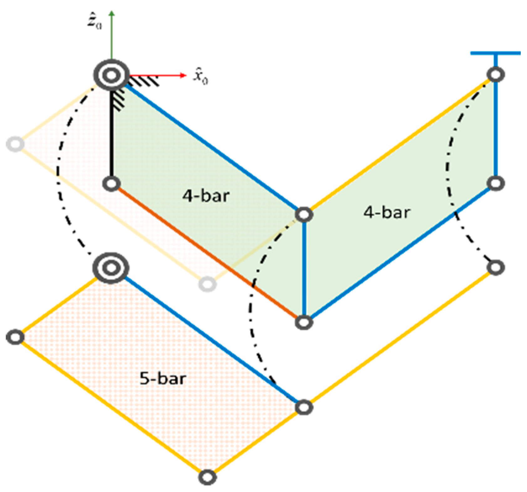
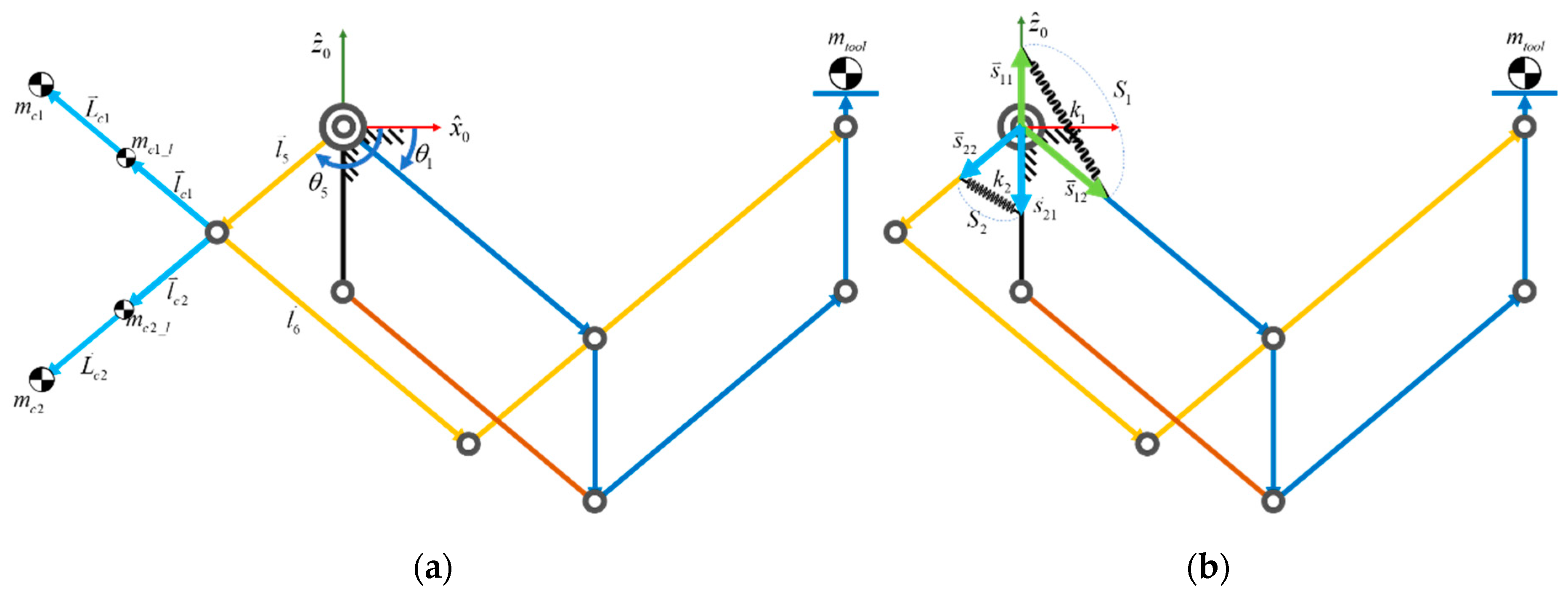
Lee et al. [34] initially suggested a stackable mechanism for single port access surgery. However, they only considered the combination of four multiple bars. Figure 1 shows the stackable parallel mechanism proposed in our study. The mechanism is constructed by stacking one double parallelogram over one five-bar. This stackable planar mechanism generates two translational degrees of freedom through the actuation of and , as shown in Figure 2. A stackable mechanism, including joint in its base position, purely creates three translational degrees of freedom. In Figure 2, the axis denotes the ground, and the mass and direction of the link are indicated. For instance, a surgical tool such as a drill or endoscope with a mass of can be installed at the distal end of the mechanism.
2.2. Conditions of Balancing
There are two methods for static balancing, namely a counterweight or a counter-spring. In previous work [11,12], a stackable mechanism using counterweights has been used, as shown in Figure 3 was investigated. The stackable mechanism using springs will be newly introduced for static balancing in this section.
In the following, we analyze the balancing equations in the planar space because the rotational motion around the -axis is not affected by gravity. The potential energy method will be employed to derive the conditions of balancing.
In Figure 2, it is assumed that each center of mass is located at the center of the link. To sustain static balancing, the potential energy of this mechanism should be constant in any configuration. In the following, the potential energy of this mechanism will be derived for the stackable linkage, counterweight, and spring part independently.
Firstly, the potential energy of this mechanism only for the masses of all links and the device mounted at the distal end can be expressed by:
where denotes the vector of the link , and the operator is the vector dot product and
The term that contains the constant potential energy is .
Secondly, the potential energy for the two counterweights depicted in Figure 3a can be similarly obtained as (5):
where
In Equations (6) and (7), and represent the masses of the two counterweights and and represent the extended link length of link and . These four parameters are used as variables for adjustable balancing when the tool at the distal end of this mechanism is changed with another one with a different mass.
Combining Equations (1) and (5), the total potential energy for counterweight balancing is represented as:
where
For static balancing over the entire workspace, and should be zero. From Equations (9) and (10), the mass of the counterweight for balancing is represented as Equations (11) and (12):
where we use the fixed extended link lengths ( and ).
Springs can be employed as the substitute of the counterweight for static balancing. Springs have many advantages in comparison to counterweights due to their light weight and small volume.
The elastic potential energy due to the spring can be obtained as per Equation (13). Here, it is assumed that the masses of the springs are negligible, and the springs have a zero-free-length.
where and , respectively, represent the elongation of each spring. The position vectors of each attachment point of the spring with respect to the origin of the base coordinate system are , , , and , respectively. The stiffness of each spring is and .
Combining Equations (1) and (14), the total potential energy for spring balancing is represented as:
where
In Equation (14), is the term that contains the constant potential energy, as per Equation (17).
For static balancing over the entire workspace, and should be zero. Then, the stiffness of the spring for balancing is represented as:
2.3. Condition of Adjustable Balancing Using a Counterweight
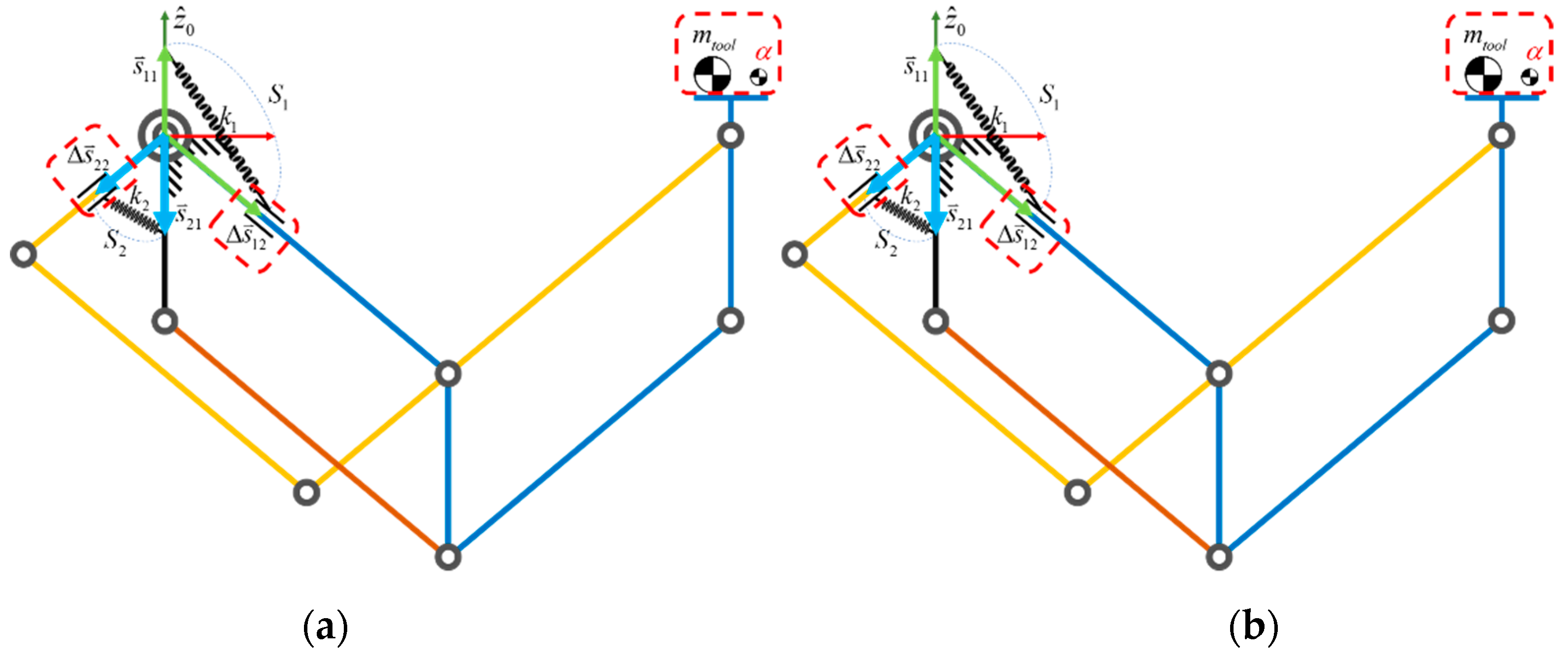
This section discusses adjustable balancing for a variable payload of . The mass stands for a variation of , such as a tool. One effective method for adjustable balancing is to use the extended link length of the counterweight. That is, as shown in Figure 4a, adjustable balancing is achieved by adjusting the extended link length of the counterweight according to the variable payload at the distal end of this mechanism. This is a typical method used in the design of a surgical microscope [20,21,22].
Here, we define the variation of the payload as and the variation of the extended link length as and , as shown in Figure 4a. For a variable payload, the total potential energy of this stackable mechanism with a counterweight is represented as:
In Equation (20), setting and as zero, the initial counterweights ( and ) are obtained as per Equations (11) and (12). Then, in the third and fourth terms of Equation (20), we can figure out the relationship between the variation of payload () and the variable length ( and ) of the counterweights as:
where the variation of payload () is associated with the ratio of and . Since is identical to , and is much smaller than (this will be explained in Section 3.1), should be larger than for the given . However, a large value of would be undesirable, since the size of the extended link length would be longer. Thus, in a real design, the maximum extended link length for will be set as 50 mm.
2.4. Conditions of Adjustable Balancing Using a Spring Only
To realize adjustable balancing for a variable payload, another effective method is to change the insertion position of the springs. As shown in Figure 4b, the insertion position of the spring will be adjusted when the payload () at the distal end is changed.
For a variable payload, the total potential energy of this stackable mechanism with springs is represented as:
In Equation (22), and are obtained as per Equations (18) and (19). Then, in the third and fourth terms of Equation (22), we can determine the relationship between the variation of payload () and the change in the insertion position ( and ) of the counter-springs as:
It is, however, noted that simply using a spring or counterweight for balancing has its own problems. If we only apply a spring, a linear actuator should be installed on the link of the stackable mechanism to change the insertion position of the spring. However, this method is too difficult to realize mechanically. It is also hard to locate a spring with the exact stiffness required. The non-linear characteristics of a spring are another factor. On the other hand, if we only apply a counterweight, installation of a linear actuator to change the extended link length is not difficult, but the counterweight would increase the inertial load of the entire system. Therefore, the operator could feel a large inertia load during high speed operation of the mechanism.
Combining the advantages of the two balancing methods, we propose a new method that combines counter-loads and springs. Table 1 compares the advantages and disadvantages of the two balancing methods and our balancing method that combines the two methods.
2.5. Condition of Balancing Using Both a Spring and a Counterweight
In this section, we discuss the case of using both a counterweight and a spring. Our strategy of using a spring and counterweight is as follows: For the given nominal payload, springs are used for initial balancing, and then counterweights are used to handle the variable payload at the distal end of the stackable mechanism.
In this case, the total potential energy of this mechanism can be written as the summation of , , and .
where
In order to sustain static balancing for any configuration, four conditions out of Equation (24) should be zero, as follows:
These conditions show that the mechanism will be balanced in the entire workspace no matter what angles and are.
3. Experiments
3.1. Adjustable Balancing Mechanism Design
The kinematic and dynamic parameters of the stackable arm are given in Appendix A. The payload corresponding to the mass of a drill attached at the distal end is also given for both the counterweight and spring balancing.
In the counterweight based balancing approach, the counterweights and were calculated as 2.331 kg and 139 g, respectively, according to Equations (11) and (12). In the design of the adjustable balancing mechanism, we set the maximally allowed extended link length ( and in Figure 4a) of the counterweight to be 50 mm. Then, considering the relationship between the counterweight and variable payload, the maximum variation of the payload was calculated as 34.75 g. This is too small compared to the nominal mass (1.28 kg) of the drill.
In the spring-based balancing approach, the stiffness of the spring was calculated as 1.351 N/mm and 1.0632 N/mm, according to Equations (18) and (19), respectively. It is, however, noted that the spring is not appropriate adjustable balancing since the insertion of this spring on the link is too limited, as shown in Figure 4b, because of its short link length. Thus, using only two springs for adjustable balancing is not appropriate.
Therefore, another adjustable balancing approach that combines both counterweights and springs is considered in this study. In fact, there are several possible combinations. From the mechanical point of view, controlling the attachment position of the spring is too difficult to realize. Therefore, we recommend that the spring should be used for supporting a large weight and that the counterweight should be used for taking care of the precise adjustable balancing.
However, using two springs and two counterweights causes the system to be too complex. Thus, we adopted an approach that employs one spring and two counterweights. The role of one spring (namely, ) is to replace a heavy counterweight By setting the mass of the two counterweights to be as small as possible, we can minimize the entire inertia of the system and can also cope with payload variation by adjusting the extended link length.
In this case, Equation (28) is modified as follows:
where by initially setting one counterweight (namely, ) as a small value, the stiffness can be determined from . Then, the other counterweight (namely, ) is obtained from , since it is the condition of . Finally, we only need to control and to perform adjustable balancing associated with a variation of payload ().
In the design process of the adjustable balancing mechanism, two counterweights were calculated as and for the given link length of The maximum variable-range of and was set as and the range of the added payload was set as a quarter of .
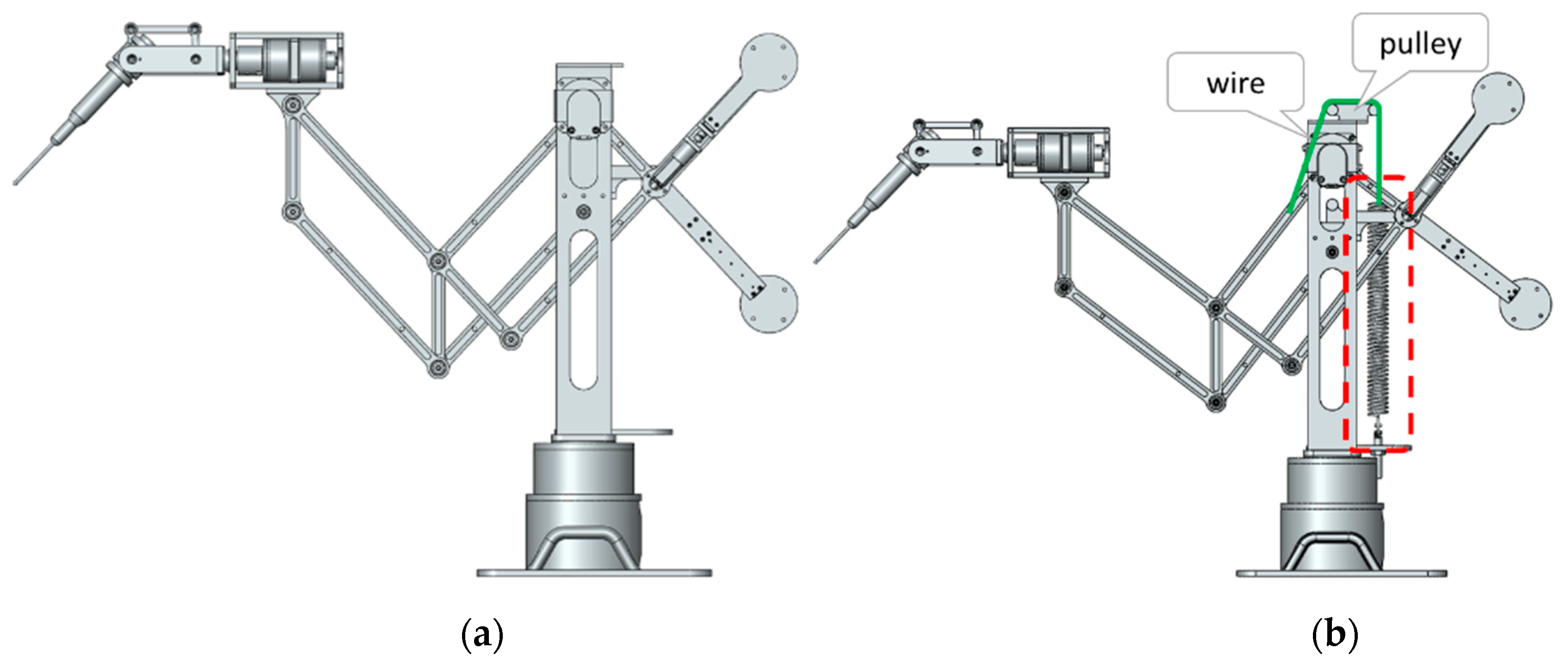
We applied the balancing arm to a surgical ear operation. This device shown in Figure 5 has 5-DOF, including a rotating module with 2-DOF mounted on the 3-DOF translational stackable mechanism. At the very distal end a drill is attached, but it is often replaced during the operation. Therefore, a variable payload occurs during the operation. In the first design, only the two counterweights are used. In the second design, one spring and two counterweights are used for gravity compensation. For an ideal spring, we used pulleys and wires.
3.2. Adjustable Balancing Experiment
We conducted experiments for two scenarios, one using only a counterweight for balancing and the other combining one spring and two counterweights.
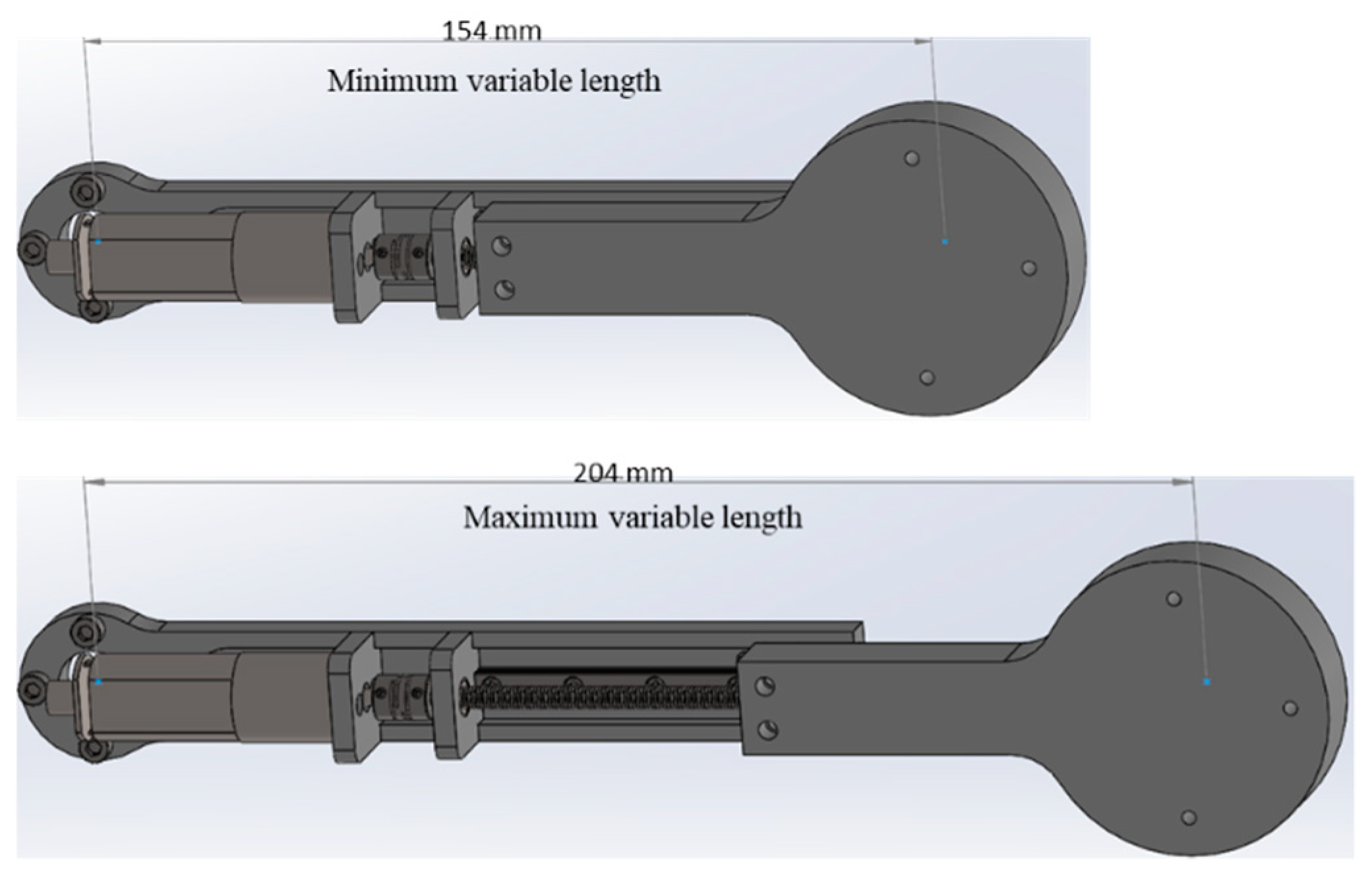
To control the extended link length of the counterweight, we designed a linear motion actuator, as shown in Figure 6. This motor is grounded at the left end of the link, and it extends the length of the link to the right. The variable range of motion is 50 mm. The variable length is also calculated via an encoder sensor mounted on the linear motion actuator.
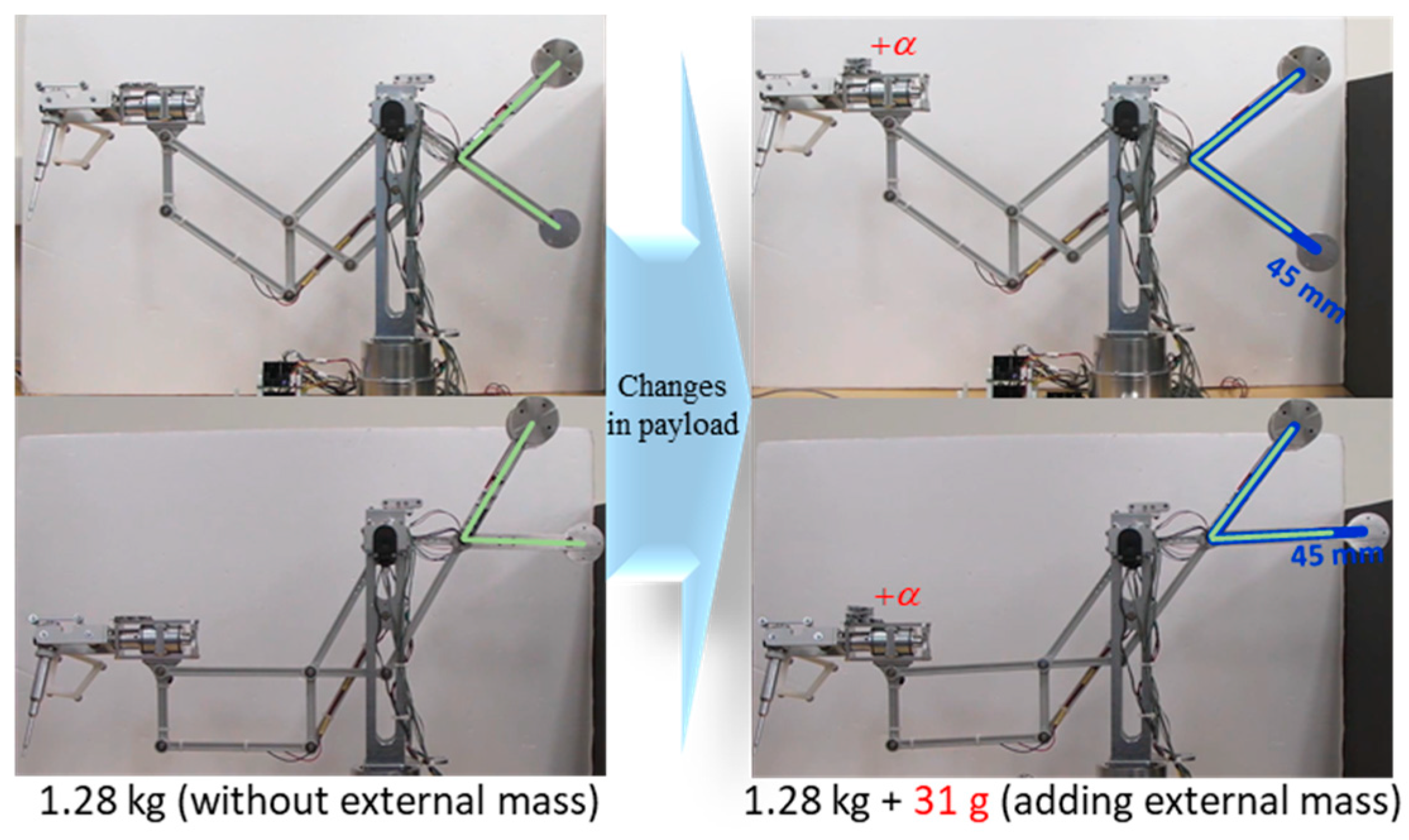
In scenario 1, only the counterweight is used. A weight of 1.28 kg was set at the distal end to balance the mechanism in the initial state. In this state, the length of the counterweight was 157 mm. To break the balancing state, we put an additional mass of 31 g at the distal end. As a result, the mechanism fell because balancing of the mechanism was no longer maintained. The encoder installed at the joints senses the movement of the mechanism when it falls. To establish gravity balancing of the mechanism, the length of the counterweight should be adjusted again. From the encoder sensor, the angular velocities of the links can be calculated. The length of the counterweight is controlled such that the angular velocities become zero. In this scenario, the length of the counterweight is increased by 45 mm within three seconds, as shown in Figure 7. In short, the added mass by 31 g requires variation of the extended link length by 45 mm, which is close to the motion range of the extended link. This implies that the allowable variation of the payload is too limited in the case of adjustable balancing by means of the counterweight alone.
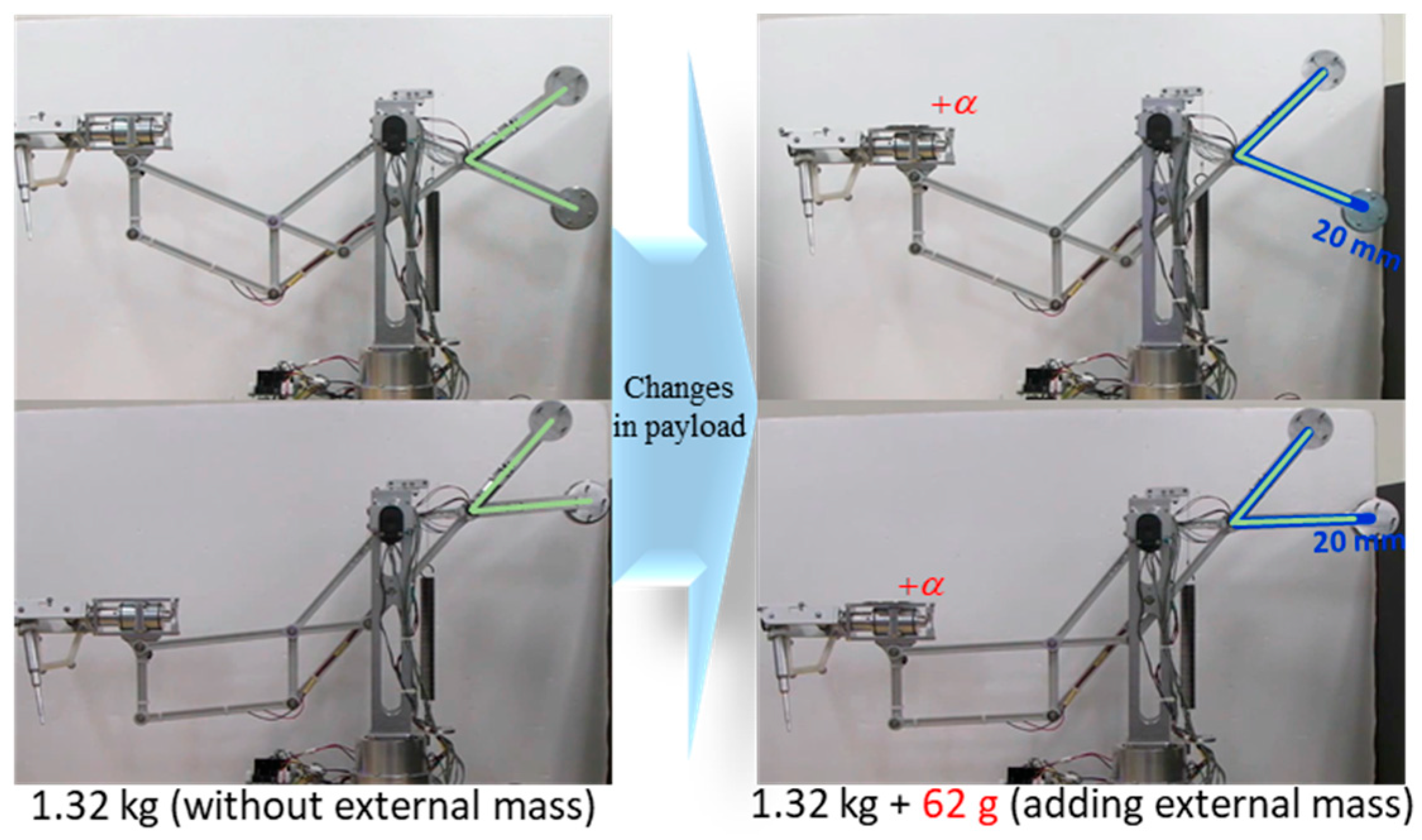
In the second scenario, both the counterweight and spring are used. A weight of 1.32 kg was set at the distal end to balance the mechanism in the initial state. In the initial state, the length of the counterweight was 154 mm. The spring only contributes to design the adjustable balancing part with minimum mass by replacing a large counterweight. Two counterweights are used to rearrange balancing by adjusting the extended link length of the counterweight when the mass at the distal end is changed.
To break the balancing state, we put a mass of 62 g at the distal end of the mechanism. To rebalance in the changed state, in the same way as in the first scenario, the link length of the counterweight was increased by 20 mm within 3 s, as shown in Figure 8. Therefore, there was still more room for extension of the link. In other words, there is still more room for the added mass at the distal end. This implies that the allowable variation of the payload is relatively large in the case of adjustable balancing by means of both a spring and a counterweight.
From these two experiments, we could confirm that the method of combining a spring and a counterweight is much more effective for adjustable balancing in a wider range of payload variations. The added external mass in the second scenario is heavier than the added external mass in the first scenario, while the increased link length of the counterweight is shorter. The video clip provided with this paper demonstrates more experimental cases.
3.3. Benefits of the Balanced Holder Mechanism
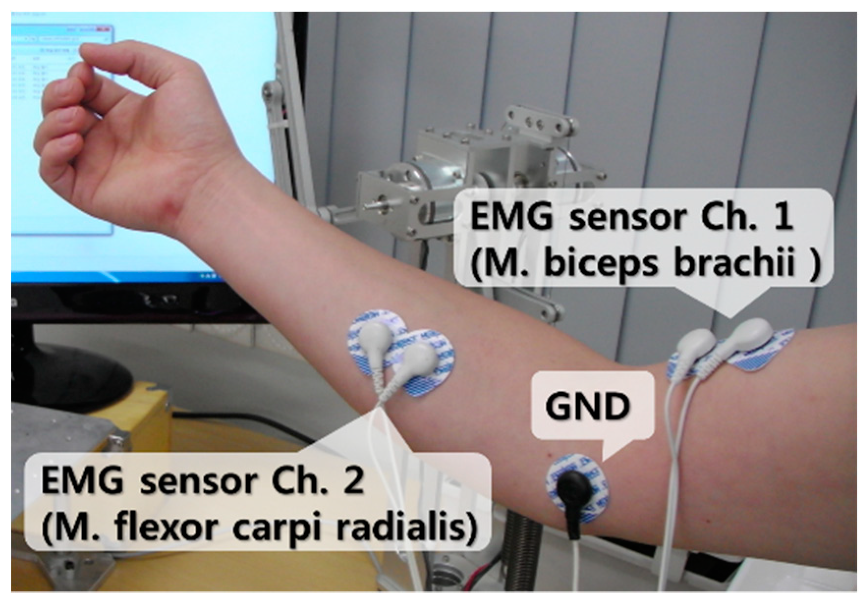
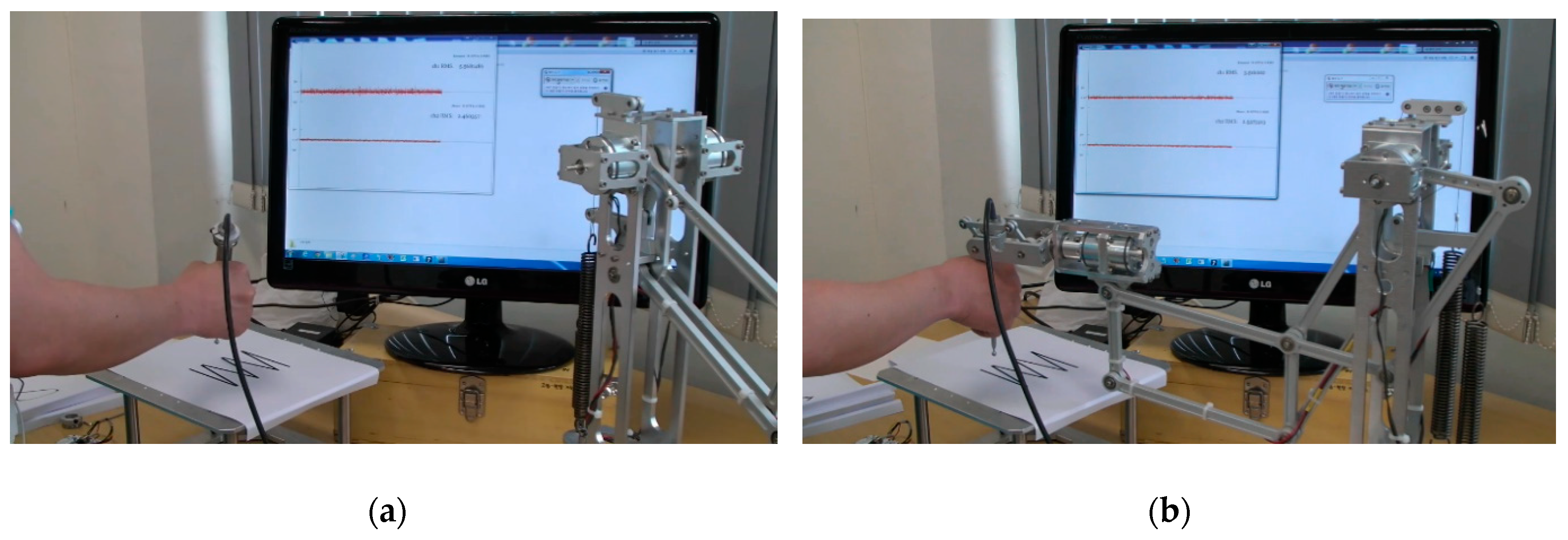
The effectiveness of the proposed gravity balancing mechanism was verified by using electromyography (EMG) sensors. The specification of the EMG sensor employed in this study is included in Appendix B. As more force is applied to the muscles, a greater EMG signal is generated. EMG sensors were attached to the M. biceps brachii and flexor carpi radial, as shown in Figure 9. The muscle signals of four users were measured. The flexor carpi radialis is responsible for the rotational motion of the wrist, and the M. biceps brachii is the muscle responsible for the rotational motion of the forearm. These two muscles are located on the outermost side of the skin and have the largest volume. Thus, we decided that these two muscles were the best place to measure signals.
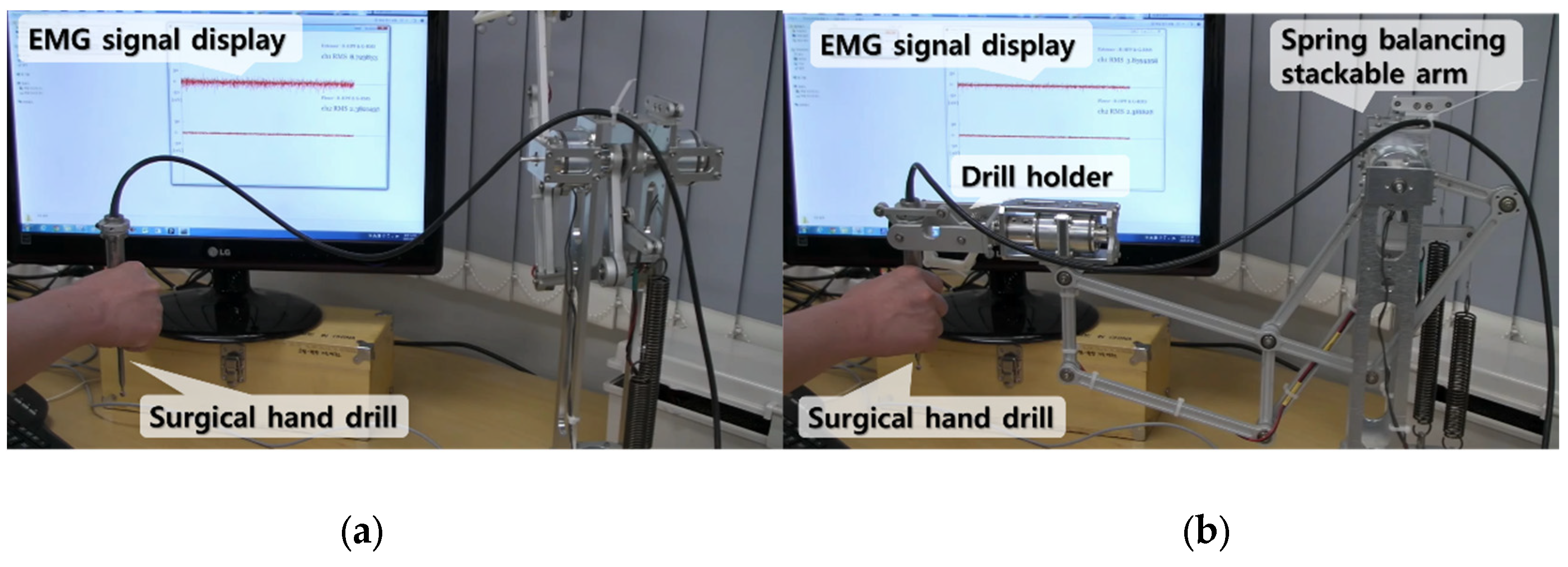
Figure 10a shows an experiment in which the user holds the surgical hand drill in the air. Figure 10b shows an experiment in which the surgical hand drill is held at the distal end of the gravity balancing arm. Then, the signal of an EMG sensor attached at the M. biceps brachii is measured in a stationary position. Only the signals of the M. biceps brachii were measured, because the flexor carpi radialis does not contribute to lifting the forearm.
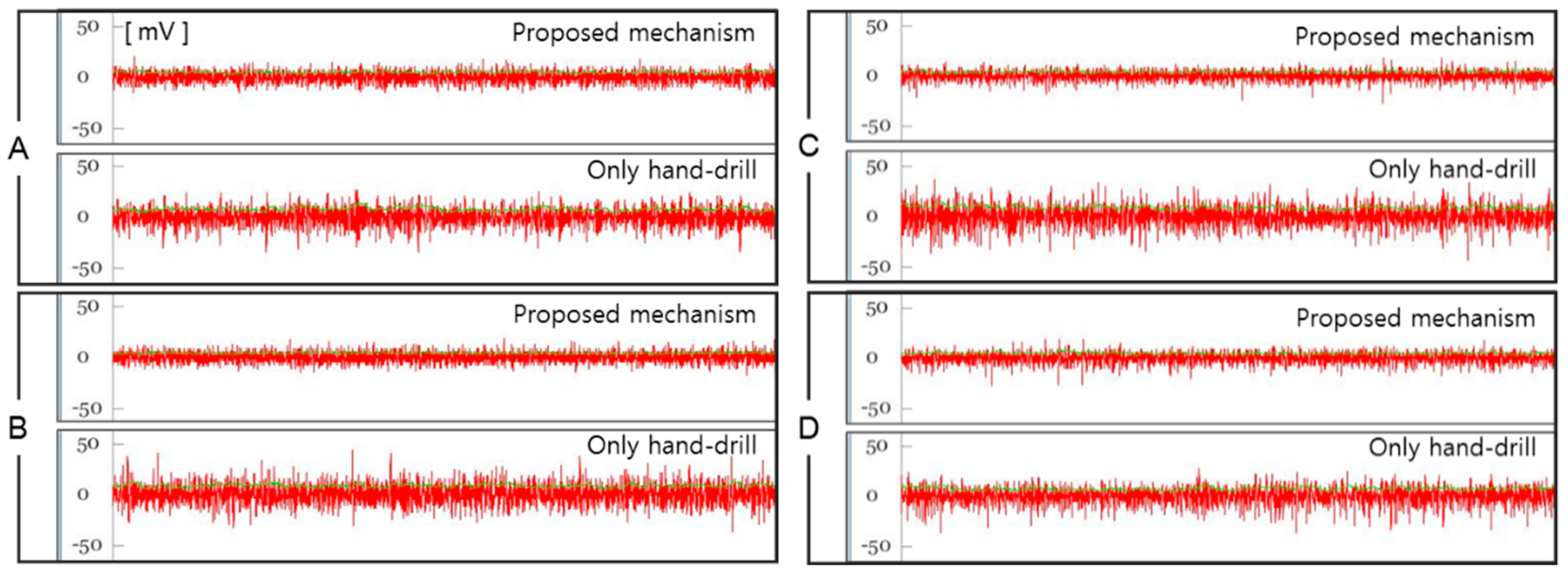
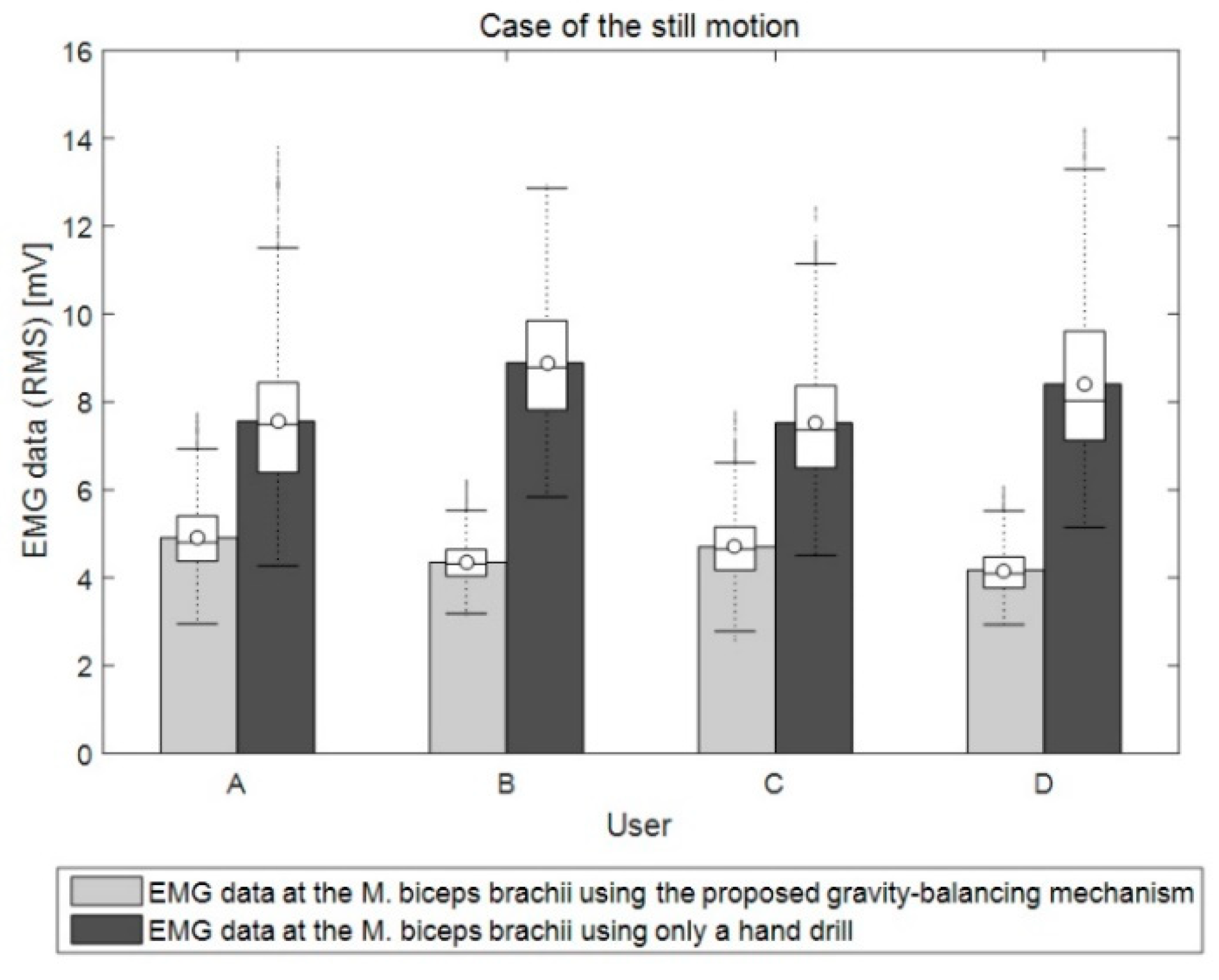
Figure 11 shows the raw data of the EMG signal for about 10 s for the two cases. Four users (referred to as A, B, C, and D) participated in the experiment. Figure 12 denotes the average RMS of the EMG raw data of the M. biceps brachii in a stationary position. Thus, it can be concluded that in the case of using the proposed mechanism, muscle fatigue is reduced because the average RMS using the gravity balancing mechanism is smaller than the case using only the hand drill.
4. Application of the Balancing Arm
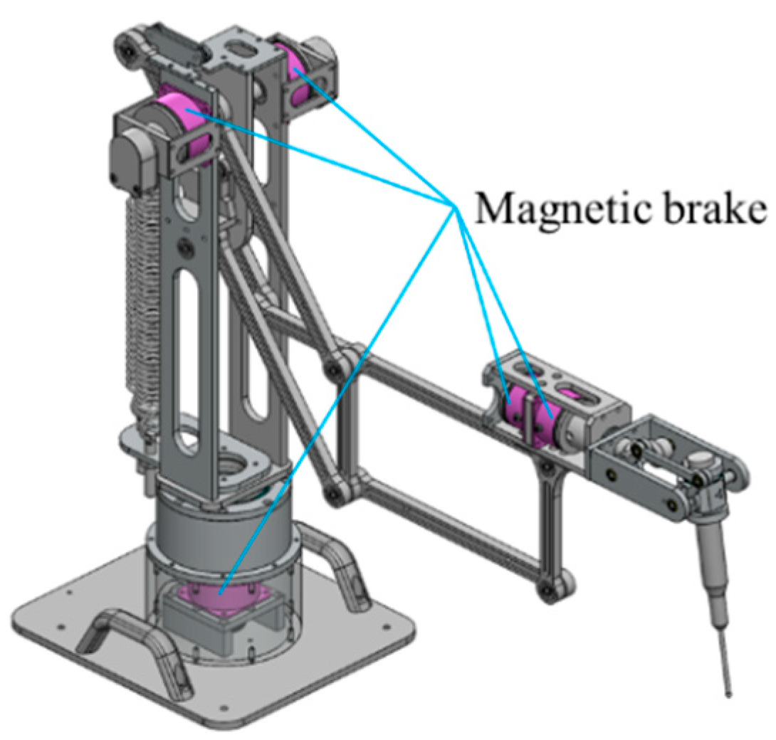
Image guided navigation systems have been popular for microsurgery. There are already many commercial products and navigation software packages for research and clinical applications. There are also many surgical procedures that use the technology. Current surgical navigation systems provide an operator with the positional data of the organs and the surgical tool inside the human body, but such information cannot prevent mistakes in operation. The otologic surgical robot using the proposed stackable mechanism employs five magnetic brakes in order to prevent mistakes. The magnetic brakes are operated when the surgical tool reaches the safety margin set by the operator so that any mistakes in surgery can be prevented. Figure 17 shows five magnetic brakes mounted on a revolute joint. Three magnetic brakes act as a brake on the stackable arm, and two magnetic brakes act as a brake on the surgical tool’s revolution.
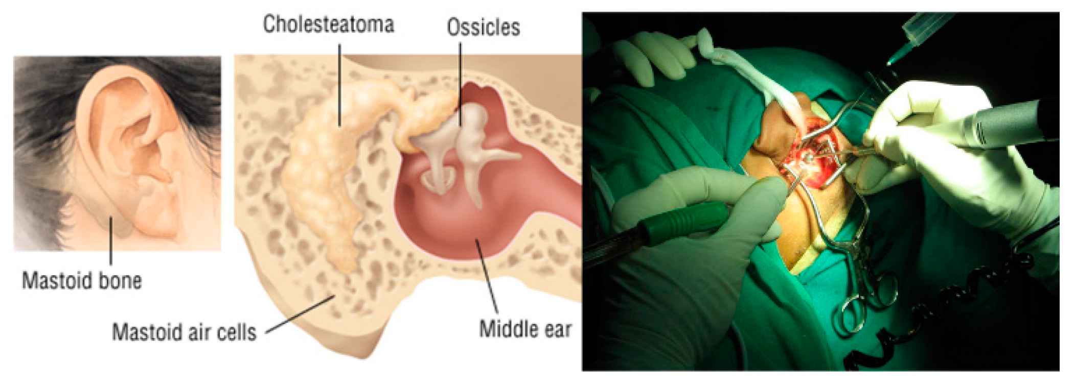
The developed otologic surgical robot was applied to a mastoidectomy, which is a surgical procedure that removes the infected portion of a mastoid bone. A mastoidectomy is a common procedure to access the inner ear area. Figure 18 shows the process of a mastoidectomy.
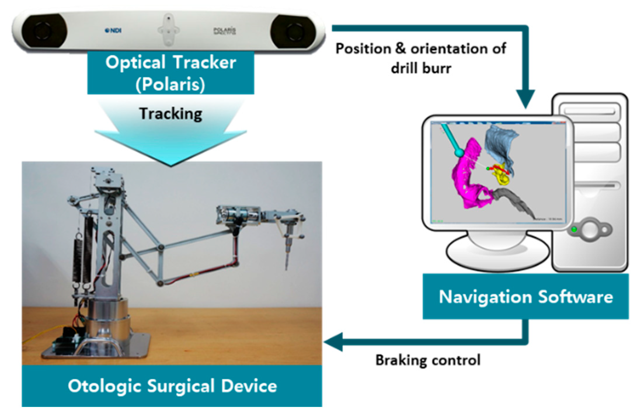
Figure 19 shows the system configuration of the otologic surgical robot system. This system consists of a surgical robot (spring balancing type), image-guided navigation software, and an optical tracker. In order to localize the positions and orientations of the surgical drill and the phantom, two probes are employed.
The navigation system is an important component of the robotic system. Some of the important organs inside the temporal bone (such as the facial nerves and carotid artery) are invisible during surgery. Thus, an image-guided navigation and warning system is necessary to help novice surgeons avoid damaging important organs inside the temporal bone.
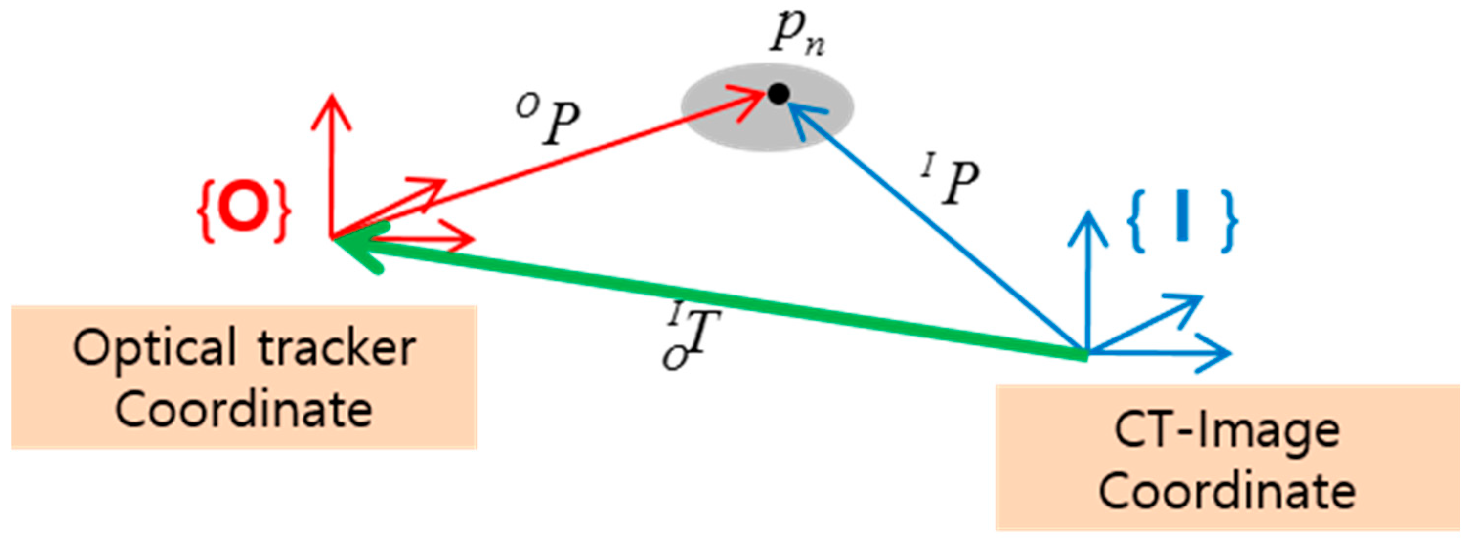
In order to integrate the navigation system with the robotic system, the patient coordinates must be registered to the CT image coordinates. The registration is done in order to find the corresponding points in the preoperative CT image data and the points on the patient’s anatomy on the operating table. Figure 20 shows the coordinate transformation between the CT image coordinates and the optical tracker coordinates. The feature point is , and is the homogenous transformation matrix that relates the optical tracker (i.e., patient) coordinate system to the image coordinate system. Six feature points were used for registration.
In order to display the position of the robot in the 3D image coordinates, registration of the robot coordinates into the image coordinates was conducted. This enabled the surgeon to ensure that the drilling did not damage important organs inside the temporal bone during operation. Furthermore, using the warning algorithm, safety problems can also be handled.
The surgeon can monitor a target lesion, the relevant organs, and the surgical drill in real-time using the image-guided navigation system. Figure 21 shows the navigation software, including the warning algorithm. The warning algorithm helps the surgeon prevent the surgical drill burr from entering critical organs.
A 3D model of the target organ was made using the CT data of a patient, and a 3-step virtual wall was formed around the target organ. The virtual wall of each step was generated at a certain distance from the surface of the target organ. The distance of each virtual wall can be modified by an operator.
If the drill burr reaches the virtual wall, the warning algorithm is activated by flickering the navigation view with a warning sound.
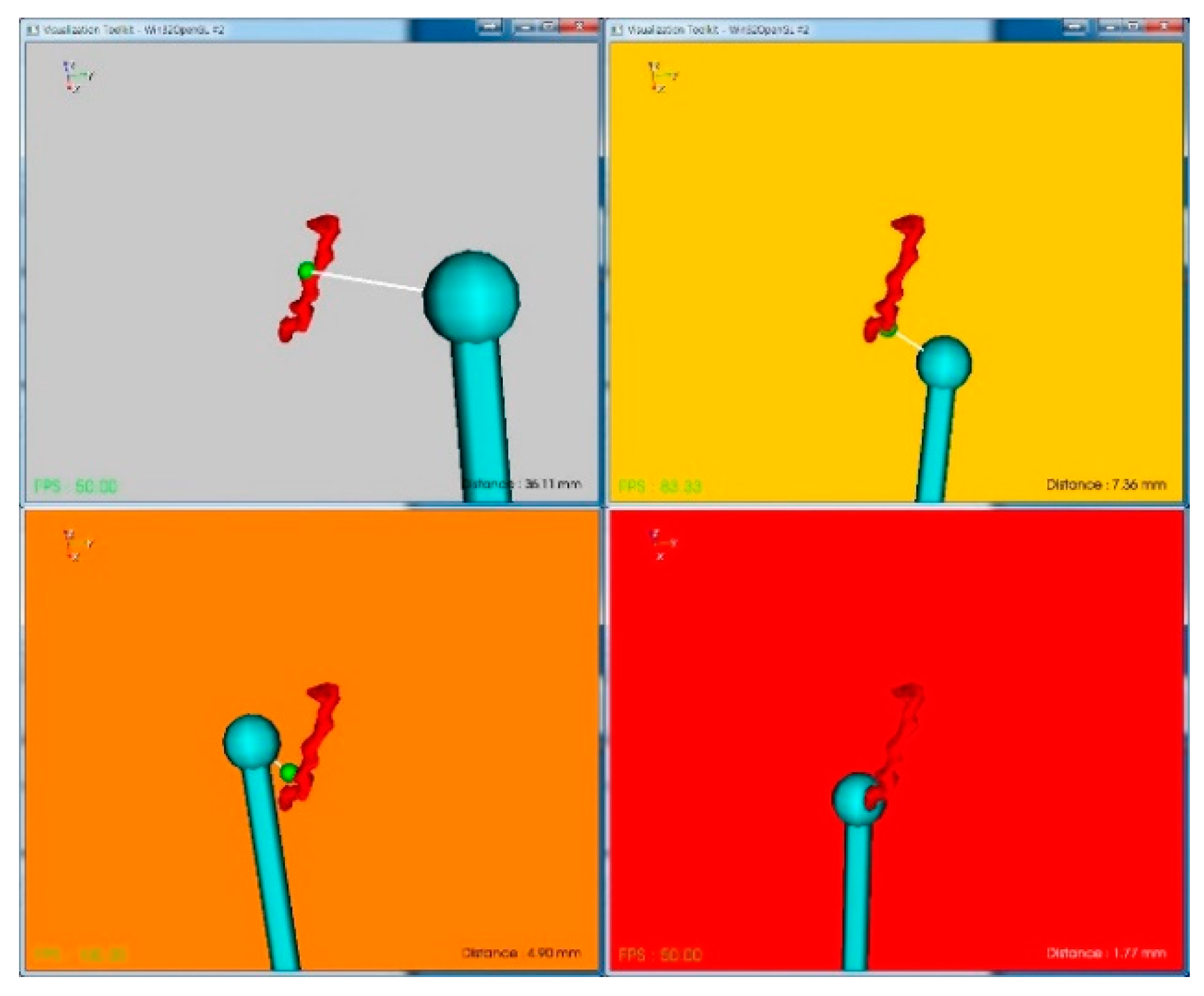
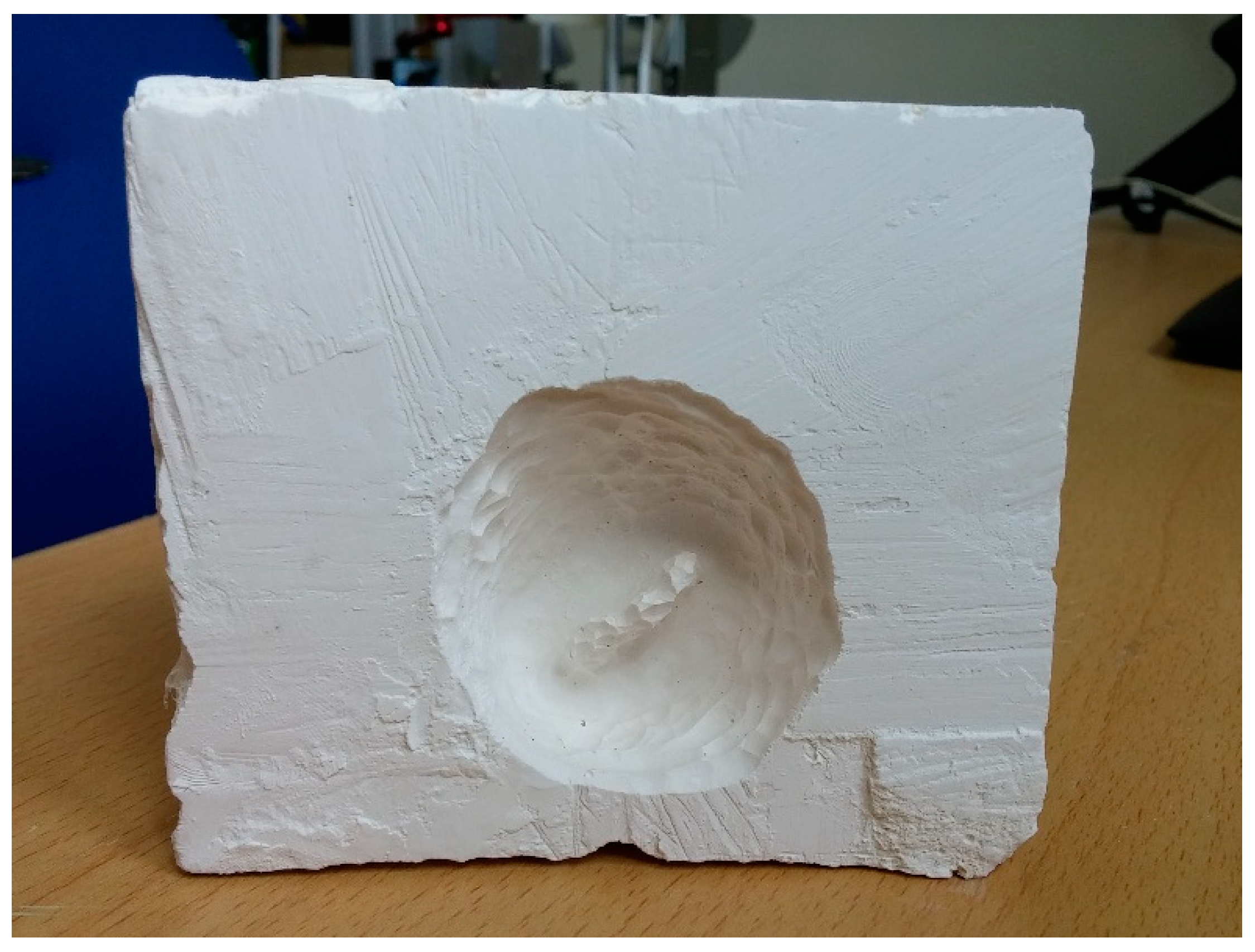
The experiment for navigation with a warning algorithm and magnetic brake was carried out by using the surgical robot and a plaster. A 3D model of a facial nerve was made by using the CT data of one patient, and a 3-step virtual wall was formed around the facial nerve. The distances from the surface of the facial nerve to the virtual wall of each step were set to 8 mm, 5 mm, and 2 mm, respectively. If the drill burr reaches a 1-step virtual wall within 8 mm of distance, a beep sound at 350 Hz is generated, and a yellow warning screen flickers. If it reaches the 2-step virtual wall at 5 mm of distance, a beep sound at 500 Hz is generated, and an orange warning screen flickers. If it reaches the 3-step wall with 2 mm of distance, a beep sounds at 700 Hz, and a red warning screen flickers. When this occurs, the drill cannot enter any further as the magnetic brake installed at the joints of the mechanism is triggered. Figure 22 shows the experimental results using plaster. The experiment was to remove the plaster while protecting the facial nerves in Figure 21. The experimental results show that the facial nerve was preserved without any damage.
In this paper, however, the TRE and FRE of the navigation software were not treated, since the purpose of this work was to test the warning algorithm and the activation of the brake. Refer to Lim [35] for measurement of the TRE and FRE for a phantom developed according to a patient’s CT data.
In conclusion, the characteristic of static balancing of the mechanism helps the surgeon manipulate the tool attached to the distal end freely without feeling much resisting force. The surgeons indicated that they felt little inertia and could operate freely, yet the haptic feeling using the magnetic brake was found to be very helpful in the experiment.
It was also noted that another role of the robotic device is as a sensor. Though it was not included in this paper, an encoder sensor can be installed at each joint of the robot to estimate the position and orientation of the device. Even for cases where the probe attached at the distal end of the robot is occluded for some reason, the navigation algorithm can still work using this internally installed sensor.
5. Discussion
In this paper, we describe the adjustable balancing method for a variable payload of a stackable mechanism. To satisfy static balancing over the entire workspace, two typical methods using a counterweight or spring were employed. It was proven that the gravity loads were fully balanced by these two types of gravity balancing mechanisms. The contribution of this paper is to suggest a new balancing method that combines the merits of the counterweight and spring. The balancing conditions for general balancing cases were derived. This new approach is appropriate to adjustable balancing when the payload at the distal end of the mechanism varies. From the experiment, we were able to demonstrate that the suggested adjustable balancing method allows a wide range of payload variation by using one spring and smaller counterweights. The balancing mechanism and navigation algorithm were successfully applied to an otological surgical procedure. Through this test experiment, the useful roles of the robotic device as a tool holder and a brake were verified. In the test to measure the operator’s fatigue, EMG sensors were employed. Though a big difference could be identified from the measured data, it still requires some improvement in terms of noise removal to clarify the difference. Depending upon the task of the operator, the muscles contributing to each task will be different. Replacing the wet-type EMG sensor with a dry-type sensor may also enhance the quality of the signal.
The applications of the proposed balancing mechanism are promising and diverse, not only in the field of medicine but also in industrial applications. Though the stackable robot employed in this research is of a passive type, the applications could also be applied to active type robots [35]. As future work, an optimal design considering the location of the counterweights and spring should be conducted. A real application to surgical operation is the final goal.
Author Contributions
J.W. contributed to the investigation, and writing: Original draft, data curation, and validation; J.-T.S. contributed to the methodology, visualization, and writing: Original draft and software; B.-J.Y. contributed to the conceptualization, project administration, supervision, and writing: Review and editing.
Funding
This work was supported by the Technology Innovation Program (or Industrial Strategic Technology Development Program-Artificial intelligence bio-robot medical convergence project) (20001257, Artificial intelligence algorithm based vascular intervention robot system for reducing radiation exposure and achieving 0.5 mm accuracy) funded by the Ministry of Trade, Industry and Energy (MOTIE, Korea), the Ministry of Health and Welfare (MOHW), the Ministry of Science and ICT (MSIT), and the Korea Evaluation Institute of Industrial Technology (KEIT).
Conflicts of Interest
The authors declare no conflict of interest.
Appendix A

Table A1.
Kinematic and dynamic parameters of the stackable mechanism.
| payload for counterweight balancing | |
| payload for a spring and counterweight balancing |
Appendix B
Table A2.
Characteristics of the EMG sensor (Arbo H124SG, COVIDIEN).
| Shape/size | Round/ø 24 mm |
| Total product surface | 452 mm2 |
| Gel area | 201 mm2 |
| Adhesive area | 251 mm2 |
| Sensor area | 80 mm2 |
| Product thickness (adapter excluded) | 1 mm |
| Adapter | Stud |
| ACZ I impedance (before defibrillation simulation) | 220 Ohm |
| DC offset voltage (before defibrillation simulation) | 0.2 mV |
| SDR (remaining potential after defibrillation simulation) | 11 mV |
| Slope (potential decline after defibrillation simulation) | 0.2 mV/s |
| COIIN (combined offset instability and inner noise) | 4 uV |
| Bias current tolerance (DC offset voltage after DC loading) | 6 mV |
References
- Mahalingam, S.; Sharan, A. The optimal balancing of the robotic manipulators. In Proceedings of the Proceesings. 1986 IEEE International Conference on Robotics and Automation, San Francisco, CA, USA, 7–10 April 1986; pp. 828–835. [Google Scholar]
- Dunlop, G.; Jones, T. Gravity counter balancing of a parallel robot for antenna aiming. In Proceedings of the 6th ISRAM, Montpellier, France, 28–30 May 1996; pp. 153–158. [Google Scholar]
- Streit, D.; Shin, E. Equilibrators for planar linkages. J. Mech. Des. 1993, 115, 604–611. [Google Scholar] [CrossRef]
- Ebert-Uphoff, I.; Gosselin, C.M.; Laliberté, T. Static balancing of spatial parallel platform mechanisms—Revisited. J. Mech. Des. 2000, 122, 43–51. [Google Scholar] [CrossRef]
- Laliberté, T.; Gosselin, C.M.; Jean, M. Static balancing of 3-DOF planar parallel mechanisms. IEEE/ASME Trans. Mech. 1999, 4, 363–377. [Google Scholar] [CrossRef]
- Wang, J.; Gosselin, C.M. Static balancing of spatial three-degree-of-freedom parallel mechanisms. Mech. Mach. Theory 1999, 34, 437–452. [Google Scholar] [CrossRef]
- Wang, J.; Gosselin, C.M. Static balancing of spatial four-degree of-freedom parallel mechanisms. Mech. Mach. Theory 2000, 35, 563–592. [Google Scholar] [CrossRef]
- Gosselin, C.M.; Wang, J. Static balancing of spatial six-degree-of-freedom parallel mechanisms with revolute actuators. J. Robot. Syst. 2000, 17, 159–170. [Google Scholar] [CrossRef]
- Russo, A.; Sinatra, R.; Xi, F. Static balancing of parallel robots. Mech. Mach. Theory 2005, 40, 191–202. [Google Scholar] [CrossRef]
- Merriam, E.G.; Howell, L.L. Non-dimensional approach for static balancing of rotational flexures. Mech. Mach. Theory 2015, 84, 90–98. [Google Scholar] [CrossRef] [Green Version]
- Simionescu, I.; Ciupitu, L.; Ionita, L.C. Static balancing with elastic systems of delta parallel robots. Mech. Mach. Theory 2015, 87, 150–162. [Google Scholar] [CrossRef]
- Liu, T.; Gao, F.; Zhao, X.; Qi, C. Static balancing of a spatial six-degree-of-freedom decoupling parallel mechanism. J. Mech. Sci. Technol. 2014, 28, 191–199. [Google Scholar] [CrossRef]
- Kim, S.J.; Cho, C. Design of static balancing mechanism for face robot. Int. J. Control Autom. Syst. 2015, 13, 194–200. [Google Scholar] [CrossRef]
- Kang, L.; Seo, J.T.; Kim, W.; Yi, B.J. Synthesis of new statically balanced parallel mechanisms. In Proceedings of the 2014 IEEE International Conference on Mechatronics and Automation, Tianjin, China, 3–6 August 2014; pp. 1102–1107. [Google Scholar]
- Agrawal, S.K.; Gardner, G.; Pledgie, S. Design and fabrication of an active gravity balanced planar mechanism using auxiliary parallelograms. J. Mech. Des. 2001, 123, 525–528. [Google Scholar] [CrossRef]
- Fattah, A.; Agrawal, S.K. On the design of reactionless 3-dof planar parallel mechanisms. Mech. Mach. Theory 2006, 41, 70–82. [Google Scholar] [CrossRef]
- Briot, S.; Arakelian, V.; Guégan, S. Paminsa: A new family of partially decoupled parallel manipulators. Mech. Mach. Theory 2009, 44, 425–444. [Google Scholar] [CrossRef]
- Tahmasebi, A.M.; Taati, B.; Mobasser, F.; Hashtrudi-Zaad, K. Dynamic parameter identification and analysis of a phantom haptic device. In Proceedings of the 2005 IEEE Conference on Control Applications, Toronto, ON, Canada, 28–31 August 2005; pp. 1251–1256. [Google Scholar]
- Kim, H.S.; Song, J.B. Multi-dof counterbalance mechanism for a service robot arm. IEEE/ASME Trans. Mech. 2014, 19, 1756–1763. [Google Scholar] [CrossRef]
- Nakamura, K.; Doi, M.; Hashimoto, T.; Nakamura, M. Holding Arm Apparatus for Medical Tool. U.S. Patent 8,910,537B2, 7 July 2011. [Google Scholar]
- Nakamura, K. Biaxial Balance Adjusting Structure for Medical Stand Apparatus. U.S. Patent 5,480,114, 2 January 1996. [Google Scholar]
- Nakamura, K.; Doi, M.; Nakamura, M. Medical Stand Apparatus. U.S. Patent 6,045,104, 4 April 2000. [Google Scholar]
- Nakamura, K.; Ota, T. Balancing Chair. U.S. Patent 5,927,815, 27 July 1999. [Google Scholar]
- Lessard, S.; Bigras, P.; Bonev, I.A. A new medical parallel robot and its static balancing optimization. J. Med. Devices 2007, 1, 272–278. [Google Scholar] [CrossRef]
- Banala, S.K.; Agrawal, S.K.; Fattah, A.; Krishnamoorthy, V.; Hsu, W.L.; Scholz, J.; Rudolph, K. Gravity-balancing leg orthosis and its performance evaluation. IEEE Trans. Robot. 2006, 22, 1228–1239. [Google Scholar] [CrossRef]
- Herder, J.L.; Vrijlandt, N.; Antonides, T.; Cloosterman, M.; Mastenbroek, P.L. Principle and design of a mobile arm support for people with muscular weakness. J. Rehabil. Res. Dev. 2006, 43, 591. [Google Scholar] [CrossRef]
- Wu, T.-M.; Wang, S.-Y.; Chen, D.-Z. Design of an exoskeleton for strengthening the upper limb muscle for overextension injury prevention. Mech. Mach. Theory 2011, 46, 1825–1839. [Google Scholar] [CrossRef]
- Ciupitu, L.; Simionescu, I.; Olaru, A. Static balancing of mechanical systems used in medical engineering field–continuous balancing. In Advanced Materials Research; Trans Tech Publications: Zürich, Switzerland, 2012; pp. 890–894. [Google Scholar]
- Lessard, S.; Bonev, I.; Bigras, P.; Briot, S.; Arakelyan, V. Optimum static balancing of the parallel robot for medical 3d-ultrasound imaging. In Proceedings of the IFTOMM 2007: 12th World Congress in Mechanism and Machine Science, Besançon, France, 18–21 June 2007. [Google Scholar]
- Dillon, N.P.; Fichera, L.; Wellborn, P.S.; Labadie, R.F.; Webster, R.J. Making robots mill bone more like human surgeons: Using bone density and anatomic information to mill safely and efficiently. In Proceedings of the 2016 IEEE/RSJ International Conference on Intelligent Robots and Systems (IROS), Daejeon, Korea, 9–14 October 2016. [Google Scholar]
- Dillon, N.P.; Ramya, B.; Antoine, M.d.F.; George, B.W.; Robert, F.L.; Thomas, J.W.; Michael, F.; Robert, J.W. Preliminary testing of a compact bone-attached robot for otologic surgery. In Medical Imaging 2014: Image-Guided Procedures, Robotic Interventions, and Modeling International Society for Optics and Photonics; International Society for Optics and Photonics: Lansdale, PA, USA, 2014. [Google Scholar]
- Seo, J.-T.; Woo, J.H.; Lim, H.; Chung, J.; Kim, W.K.; Yi, B.-J. Design of an antagonistically counter-balancing parallel mechanism. In Proceedings of the 2013 IEEE/RSJ International Conference on Intelligent Robots and Systems, Tokyo, Japan, 3–7 November 2013; pp. 2882–2887. [Google Scholar]
- Seo, J.T.; Woo, J.H.; Lim, H.; Yi, B.J. Design of a new counter-balancing stackable mechanism. In Proceedings of the 2014 IEEE International Conference on Robotics and Automation (ICRA), Hong Kong, China, 31 May–7 June 2014; pp. 2372–2377. [Google Scholar]
- Lee, H.; Choi, Y.; Yi, B.J. Stackable 4-bar manipulators for single port access surgery. IEEE/ASME Trans. Mech. 2011, 17, 157–166. [Google Scholar] [CrossRef]
- Lim, H.; Matsumoto, N.; Cho, B.; Hong, J.; Yamashita, M.; Hashizume, M.; Yi, B.J. Semi-manual mastoidectomy assisted by human–robot collaborative control—A temporal bone replica study. Auris Nasus Larynx 2016, 43, 161–165. [Google Scholar] [CrossRef] [PubMed]
Figure 1.
The stackable mechanism.

Figure 2.
Actuation of the stackable mechanism.

Figure 3.
Balancing method of the stackable device. (a) Balancing mechanism using counterweights. (b) Balancing mechanism using springs.
Figure 3.
Balancing method of the stackable device. (a) Balancing mechanism using counterweights. (b) Balancing mechanism using springs.

Figure 4.
Adjustable balancing stackable mechanism. (a) Adjustable balancing mechanism using counterweights. (b) Adjustable balancing mechanism using springs.
Figure 4.
Adjustable balancing stackable mechanism. (a) Adjustable balancing mechanism using counterweights. (b) Adjustable balancing mechanism using springs.

Figure 5.
Ear surgical device (a) balancing by counterweight only. (b) Balancing by both a counterweight and spring.
Figure 5.
Ear surgical device (a) balancing by counterweight only. (b) Balancing by both a counterweight and spring.

Figure 6.
Variable extended link.

Figure 7.
Balancing by counterweight only.

Figure 8.
Balancing using a counterweight and a spring.

Figure 9.
Attaching position of the electromyography (EMG) sensor.

Figure 10.
Test at a stationary position: (a) Using only a hand drill and (b) using the proposed spring balancing mechanism.
Figure 10.
Test at a stationary position: (a) Using only a hand drill and (b) using the proposed spring balancing mechanism.

Figure 11.
Raw data of the EMG signal for the four users.

Figure 12.
Average root mean square (RMS) value of the EMG sensor at the M. biceps brachii when measured at a stationary position.
Figure 12.
Average root mean square (RMS) value of the EMG sensor at the M. biceps brachii when measured at a stationary position.

Figure 13.
Test environment for the infinity shape motion: (a) Using only a hand drill and (b) using the proposed spring balancing mechanism.
Figure 13.
Test environment for the infinity shape motion: (a) Using only a hand drill and (b) using the proposed spring balancing mechanism.

Figure 14.
Test environment for the zigzag shape motion: (a) Using only a hand drill and (b) using the proposed spring balancing mechanism.
Figure 14.
Test environment for the zigzag shape motion: (a) Using only a hand drill and (b) using the proposed spring balancing mechanism.

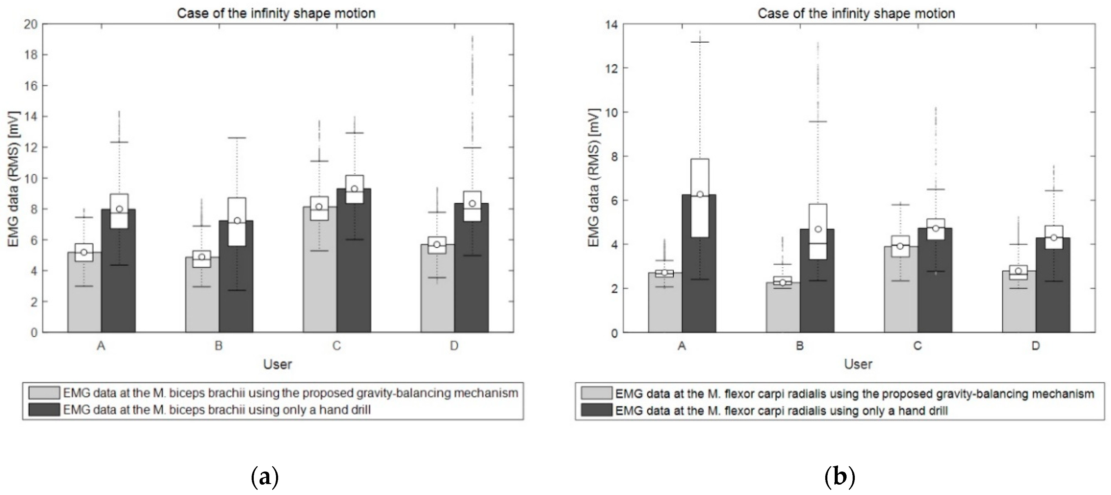
Figure 15.
Box plot of the EMG data in the case of the infinity shape motion: (a) Average RMS of the EMG sensor at the M. biceps brachii and the (b) average RMS of the EMG sensor at the M. flexor carpi radialis.
Figure 15.
Box plot of the EMG data in the case of the infinity shape motion: (a) Average RMS of the EMG sensor at the M. biceps brachii and the (b) average RMS of the EMG sensor at the M. flexor carpi radialis.

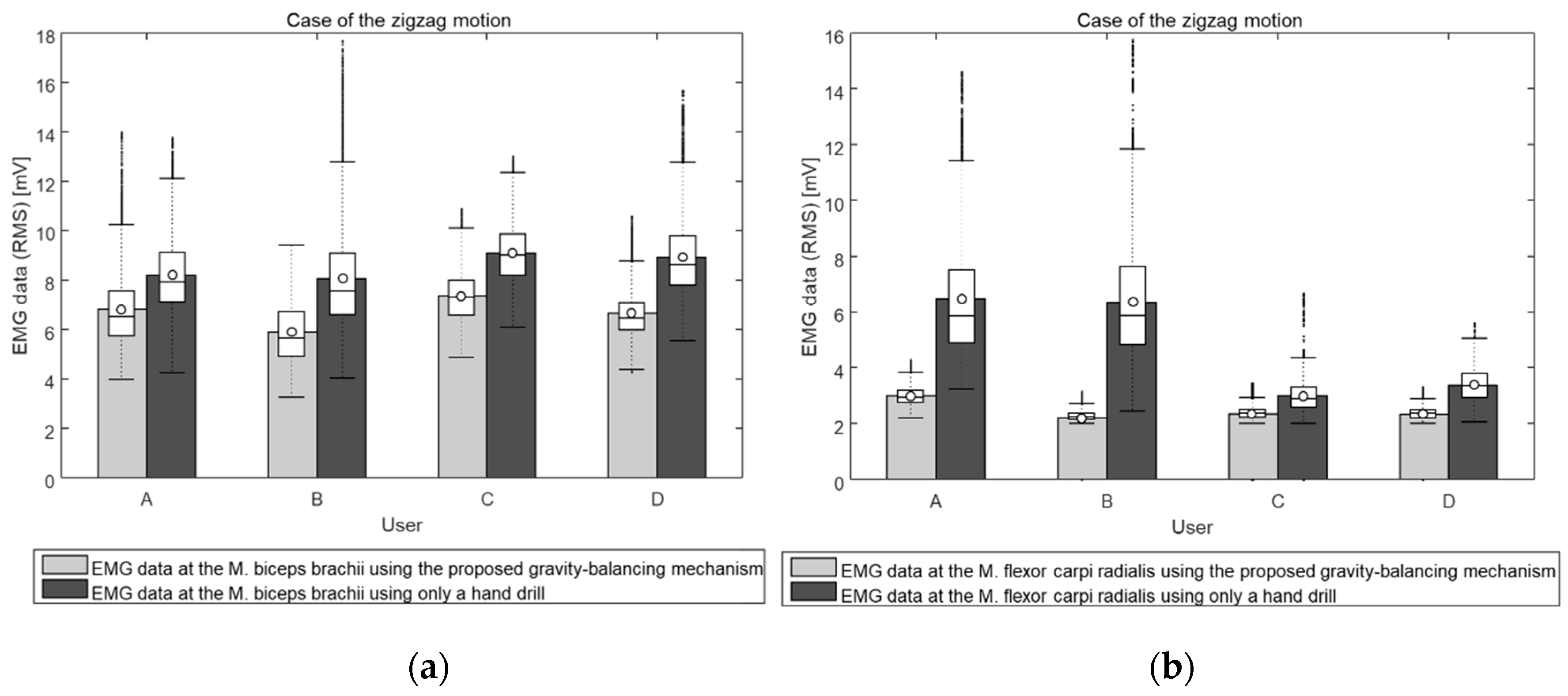
Figure 16.
Box plot of the EMG data in the case of the zigzag motion: (a) Average RMS of the EMG sensor at the M. biceps brachii and the (b) average RMS of the EMG sensor at the M. flexor carpi radialis.
Figure 16.
Box plot of the EMG data in the case of the zigzag motion: (a) Average RMS of the EMG sensor at the M. biceps brachii and the (b) average RMS of the EMG sensor at the M. flexor carpi radialis.

Figure 17.
Magnetic brakes.

Figure 18.
Mastoidectomy.

Figure 19.
System configuration.

Figure 20.
Registration between optical tracker and CT-image coordinate.

Figure 21.
Navigation software including the warning algorithm.

Figure 22.
Warning and braking experiment.

Table 1.
Comparison of the three balancing methods.
| Method | Advantage | Disadvantage |
|---|---|---|
| Counterweight | Mechanically easy to assemble the linear actuator | Large mass of the counterweight High inertia |
| Spring | User feels low inertia | Nonlinear stiffness of the spring Difficult to assemble the linear actuator |
| Counterweight and Spring | User feels low inertia Mechanically easy to assemble the linear actuator Wide range of adding mass | Higher cost |
© 2019 by the authors. Licensee MDPI, Basel, Switzerland. This article is an open access article distributed under the terms and conditions of the Creative Commons Attribution (CC BY) license (http://creativecommons.org/licenses/by/4.0/).
Share and Cite
MDPI and ACS Style
Woo, J.; Seo, J.-T.; Yi, B.-J. A Static Balancing Method for Variable Payloads by Combination of a Counterweight and Spring and Its Application as a Surgical Platform. Appl. Sci. 2019, 9, 3955. https://doi.org/10.3390/app9193955
AMA Style
Woo J, Seo J-T, Yi B-J. A Static Balancing Method for Variable Payloads by Combination of a Counterweight and Spring and Its Application as a Surgical Platform. Applied Sciences. 2019; 9(19):3955. https://doi.org/10.3390/app9193955
Chicago/Turabian StyleWoo, Jaehong, Jong-Tae Seo, and Byung-Ju Yi. 2019. "A Static Balancing Method for Variable Payloads by Combination of a Counterweight and Spring and Its Application as a Surgical Platform" Applied Sciences 9, no. 19: 3955. https://doi.org/10.3390/app9193955
Note that from the first issue of 2016, this journal uses article numbers instead of page numbers. See further details here.