Design and Implementation of a Multi-Function Gripper for Grasping General Objects


Department of Industry-University Cooperation Foundation, Hanyang University ERICA, 55 Hanyangdaehak-ro, Sangnok-gu, Ansan, Gyeonggi-do 15588, Korea
*
Author to whom correspondence should be addressed.
Appl. Sci. 2019, 9(24), 5266; https://doi.org/10.3390/app9245266
Submission received: 17 October 2019
/
Revised: 26 November 2019
/
Accepted: 27 November 2019
/
Published: 4 December 2019
(This article belongs to the Special Issue Object Recognition, Robotic Grasping and Manipulation)
Abstract
:Featured Application
A multi-function grasping system is developed to grasp various objects in different working environments, such as piece-picking in warehouses and fulfillment centers.
Abstract
The development of a reliable pick-and-place system for industrial robotics is facing an urgent demand because many manual-labor works, such as piece-picking in warehouses and fulfillment centers tend toward automation. This paper presents an integrated gripper that combines a linkage-driven underactuated gripper with a suction gripping system for picking up a variety of objects in different working environments. The underactuated gripper consists of two fingers, and each finger has three degrees of freedom that are obtained by stacking one five-bar mechanism over one double parallelogram. Furthermore, each finger is actuated by two motors, both of which can be installed at the base owing to the special architecture of the proposed robotic finger. A suction cup is used to grasp objects in narrow spaces and cluttered environments. The combination of the suction and traditional linkage-driven grippers allows stable and reliable grasping under different working environments. Finally, practical experiments using a wide range of objects and under different grasping scenarios are performed to demonstrate the grasping capability of the integrated gripper.
1. Introduction
The growth in industrial automation indicates that the human–robot–environment interaction will become a common work scenario in many robot applications such as personal, service, and medical robots. In particular, robotic end-effectors such as grippers/hands are expected to frequently experience physical contact with the environment. Thus, to ensure a stable and reliable grasping, the grippers should be designed to be multi-functional.
So far, a large number of robotic hands/grippers have been developed to grasp various objects. Among them, multi-fingered anthropomorphic robotic hands have been proposed to attain dexterous manipulation similar to a human hand. The well-known designs include the DLR hand [1], Shadow hand [2], Nasa Robonaut 2 hand [3], and many others. These anthropomorphic hands, especially the fully actuated type, can be used to achieve dexterity similar to the human hand. However, because of multiple degrees of freedom (DOFs) and multiple actuators, the entire hand system is generally bulky and costly. Furthermore, a complicated control system is required to simultaneously operate multiple actuators located at different fingers. Because of the aforementioned reasons, very few anthropomorphic hands have been employed in the industry, and most of them are still used only in educational institutions.
To overcome the disadvantages of anthropomorphic hands, many non-anthropomorphic hands have been developed. Among them, the underactuated robotic hands, which are developed to reduce the number of actuators and complexity while preserving the relatively high versatility, have received particular attention [4,5,6,7,8,9,10,11,12,13,14,15,16,17]. These hands have been widely used in the automation industry and daily-life applications. The pioneer designs include the Barret [18], Reflex [19], and Robotiq two-finger and three-finger hands [20,21]. For the underactuated robotic grippers/hands, passive elements such as springs, mechanical stoppers, or compliant links are generally required to automatically adapt the robotic finger to the shape of the object.
The aforementioned multi-fingered robotic hands/grippers can be used to safely and stably grasp objects in open space. However, in cluttered-environment applications where objects are surrounded by one another, the use of multi-fingered robotic hands is not suitable because physical contacts with the objects to be grasped may occur. In comparison, suction grippers are more suitable for grasping objects in cluttered narrow spaces [22,23,24,25,26]. However, because the suction cup is soft, suction grasping might be not stable in relatively high-speed, high-acceleration, or high-payload applications. Furthermore, the contact area between the soft suction cup and object influences the suction-gripping force. In addition, the contact area may vary with respect to the different shapes and materials of the object to be grasped. For example, the suction cup may fail to grasp objects made of fabric materials or those with multiple holes. To achieve stable and reliable grasping, we develop a multi-function gripper that combines a new two-fingered underactuated gripper with a vacuum grasping system. This multi-function gripper can be used to grasp general objects in different environments.
This paper is structured as follows. Section 2 describes in detail the architecture of the multi-function gripper. Section 3 discusses the analysis of various grasping modes and grasping strategies in different working environments. Section 4 presents the implementation of real-world experiments using a six-DOF commercial robotic arm. Section 5 provides the discussion and conclusion.
2. Architecture Description of the Multi-Function Gripper
In this section, the architecture of the proposed three-DOF robotic finger and the two-fingered underactuated gripper is presented in detail. The suction system and its integration into the gripper are introduced.
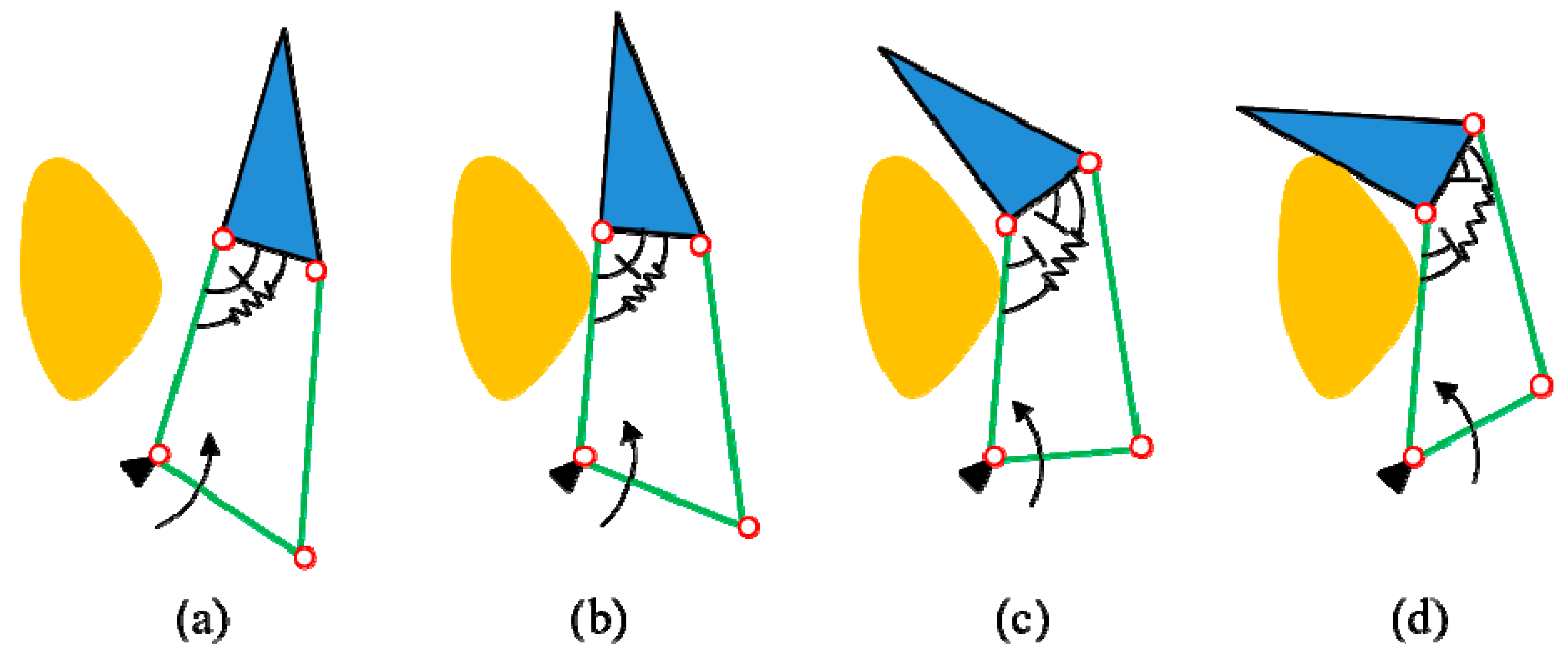
As we mentioned earlier, underactuation can be achieved through using passive elements such as springs and mechanical stoppers. First, a demonstration of the closing sequence of a two-phalanx robotic finger is shown in Figure 1 to clearly understand the working principle of underactuation. This finger is actuated by the lower link indicated by the arrow. This finger has two phalanxes, whereas only one actuator is used for control. The spring and mechanical stopper are used to constrain the relative motion between the two phalanxes. First, before the proximal phalanx makes physical contact with the object to be grasped, the whole finger moves as a single rigid body, as shown in Figure 1a,b. Second, when the proximal phalanx makes physical contact with the object, it stops its movement. In this case, the actuation toque overcomes the preloading of the spring, and the distal phalanx continues to rotate [as shown in Figure 1c] relative to the proximal phalanx until it also makes physical contact with the object [as shown in Figure 1d]. It is noted that the finger closing sequence is automatically generated by continuous actuation of the lower link, as indicated by the arrow.
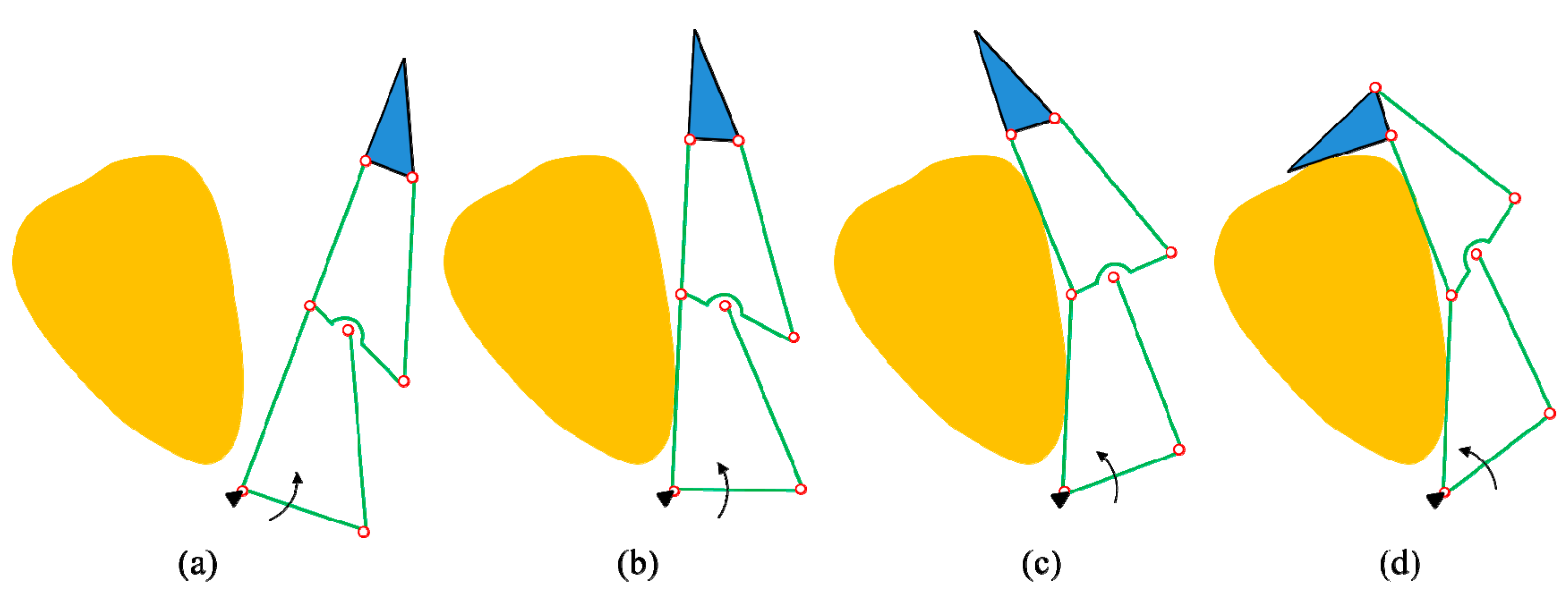
Similarly, the closing sequence of the traditional three-phalanx robotic finger is shown in Figure 2, which is an underactuated finger that can be controlled using only one motor. Robotiq three-finger adaptive gripper [21] is based on the modification of this principle. The springs and mechanical stoppers are installed at the pivot joint between each phalanx. Actuating the lower link (indicated by the arrow) can automatically generate this closing sequence. The three phalanxes will make contact with the object in sequence. However, this underactuated robotic finger can only be used to perform shape-adaptive grasping. In a real world scenario, we expect the robotic finger to have multiple grasping modes such as parallel and shape-adaptive grasping. In this case, special design architecture of the three-phalanx robotic finger needs to be developed. Moreover, sometimes, we need to fully actuate a linkage-driven robotic finger to achieve high dexterity. With respect to the three-phalanx robotic finger shown in Figure 2, we cannot install all actuators at the base. Floating actuators will generate large moving inertia, and the size of the floating actuator is confined to the mechanical dimension of the finger.
Thus, the initial motivation of this research is to propose a new three-phalanx robotic finger that can achieve multiple grasping modes. To fully actuate this three-phalanx robotic finger, another design goal is to install all the actuators at the base. Furthermore, the motion of the distal phalanx is expected to be decoupled from the proximal and intermediate phalanxes to reduce control complexity and increase dexterity. Finally, a suction-gripping system is integrated to grasp objects in cluttered, narrow spaces.
2.1. Three-DOF Linkage-Driven Robotic Finger
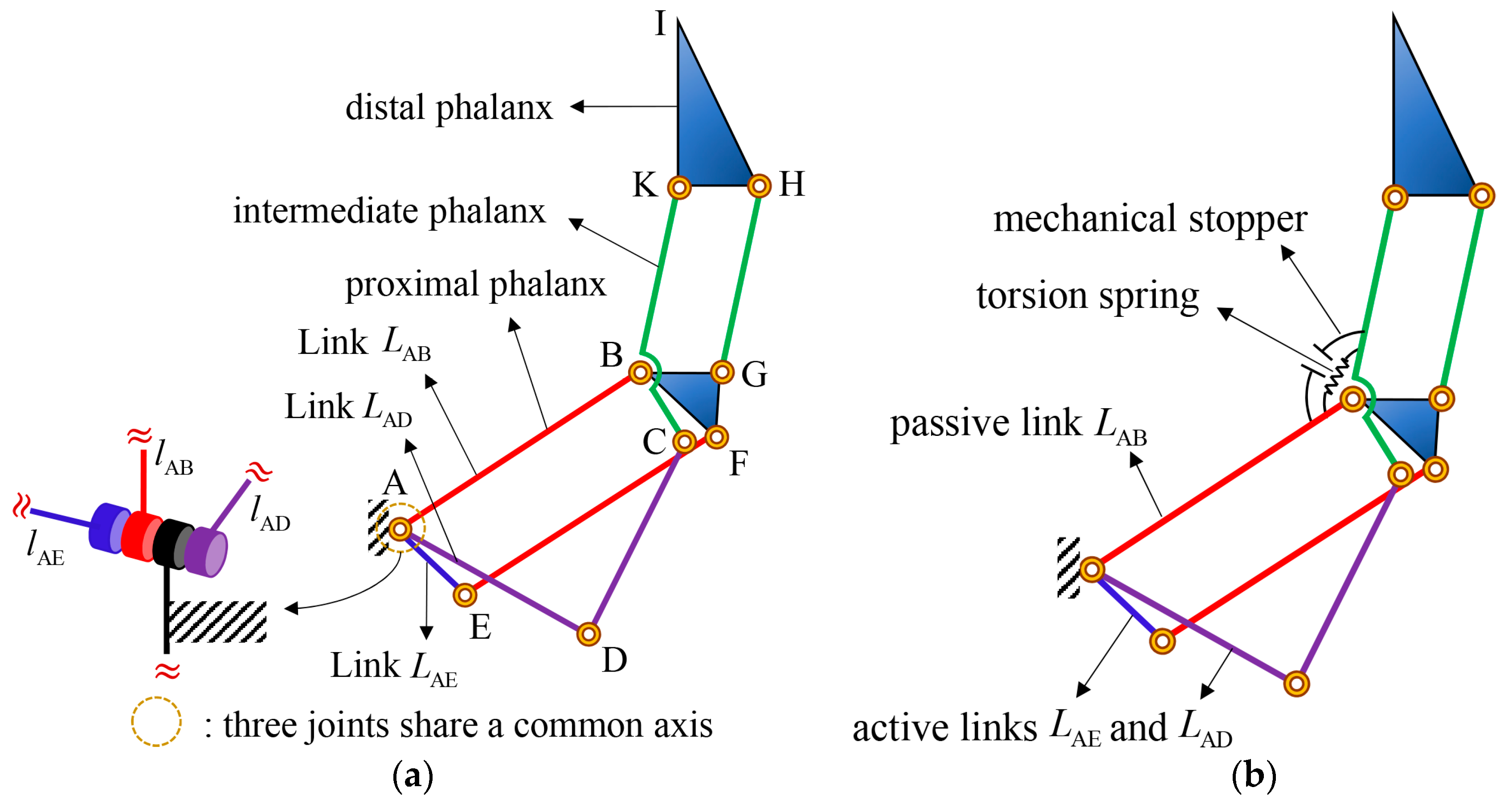
In this paper, we propose a three-DOF linkage-driven robotic finger whose all three actuators required for full actuation can be installed at the base, and the orientation of the distal phalanx can be independently controlled. The schematic diagram of the three-DOF linkage-driven robotic finger is shown in Figure 3. We can see that this finger mechanism is constructed by stacking one five-bar mechanism (ABCD) over one double parallelogram (ABFE, BKHG). Figure 3a shows that three independent links (, , and ) can be used to fully control this three-phalanx robotic finger. Because three joints driving those three independent links are coaxial, all three actuators required for full actuation can be installed at the base.
2.2. Two-Finger Underactuated Gripper and Integrated Suction System
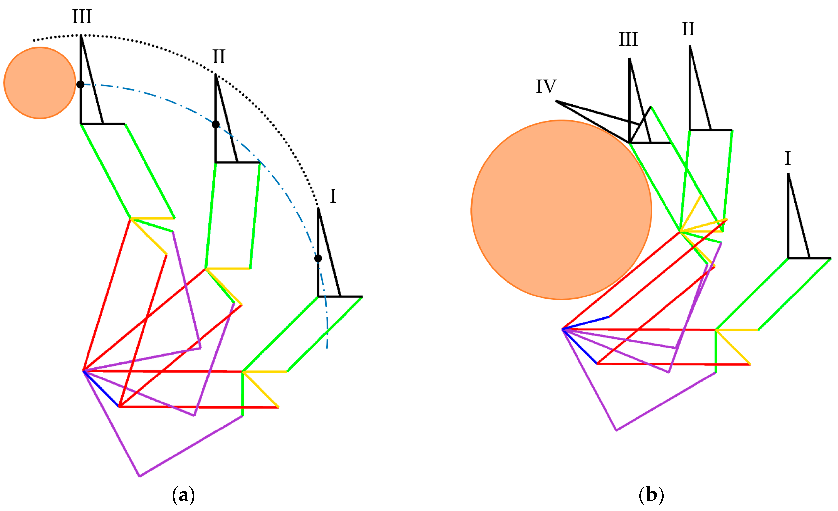
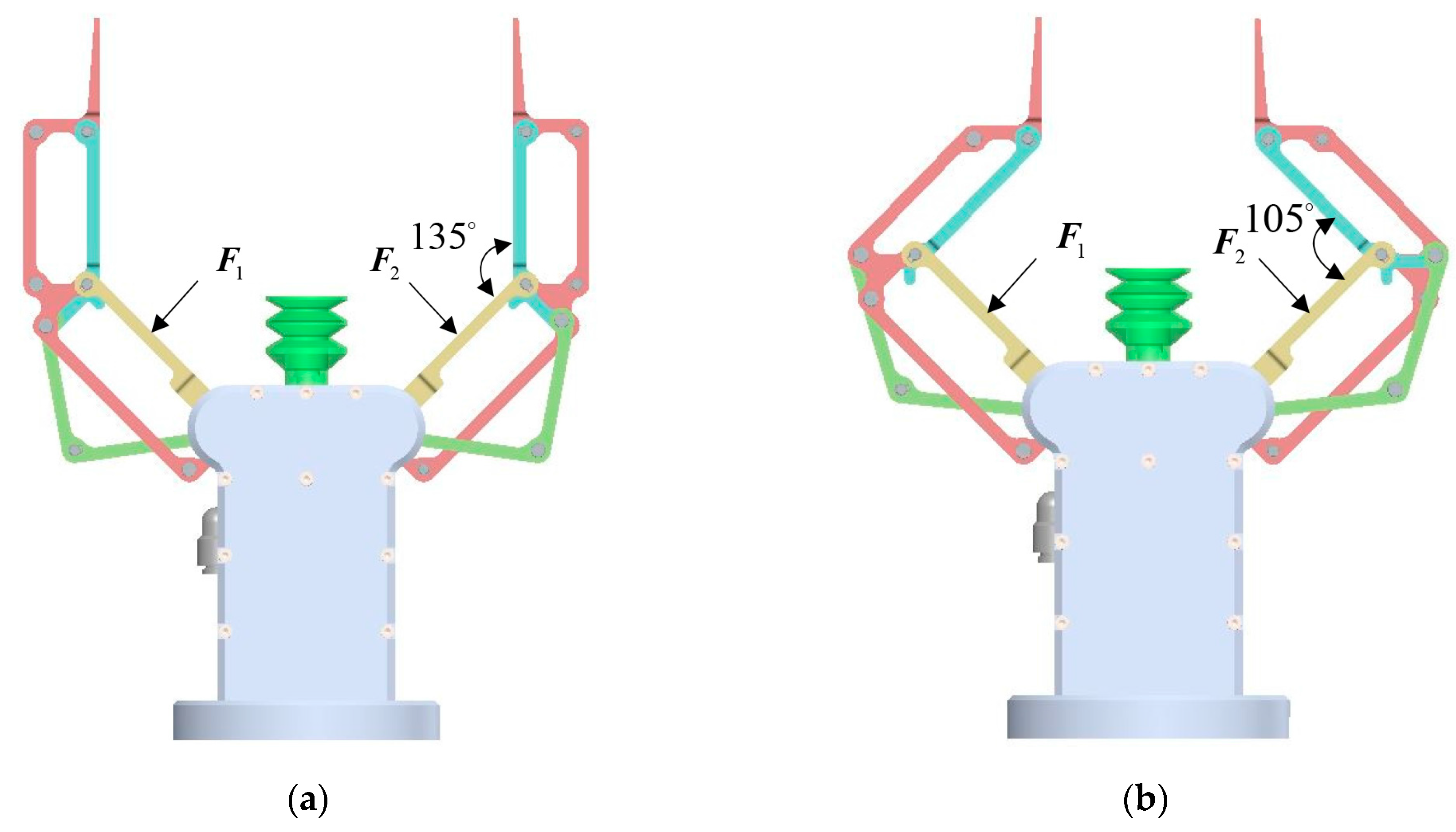
Even though the robotic finger shown in Figure 3a can be fully actuated to achieve high dexterity, in the current study, we focus on developing an underactuated type that can realize parallel and shape-adaptive grasping. Similar to the two-phalanx underactuated robotic finger shown in Figure 1, one torsion spring and one mechanical stopper are installed between the proximal and intermediate phalanxes to realize an underactuated finger, as shown in Figure 3b. The torsion spring is used to prevent free motion between the proximal and intermediate phalanxes. The proximal and intermediate phalanxes are passively coupled with each other by the torsion spring and mechanical stopper. There exist two independent motions in this finger, i.e., the open-close motion of the finger and distal-phalanx orientation adjustment. Two motors are required to control this underactuated finger. One motor rotating link is used to control the open-close motion of the finger, and the other one rotating link is used to control the orientation of the distal phalanx. Thus, the open-close motion and distal-phalanx orientation adjustment are decoupled from each other. The grasping sequences of the parallel and shape-adaptive grasping are shown in Figure 4a,b, respectively.
For the parallel grasping shown in Figure 4a, when independent link is actuated and if no external contact occurs at the proximal phalanx, the proximal and intermediate phalanxes move together as a single rigid body (from phase I to phase III) because the torsion spring prevents a relative free motion between them. In general, preloading of the torsion spring is required to prevent any undesired motion due to the gravity and inertia effects during the open-close motion.
For the shape-adaptive grasping shown in Figure 4b, if no external contact occurs at the proximal phalanx, activating independent link generates a free open-close motion (from phase I to phase II), similar to that of the parallel grasping. Starting from phase II, physical contact occurs between the object to be grasped and the proximal phalanx. In this case, the proximal phalanx stops the movement, and the intermediate phalanx continues to move against the torsion spring until it makes contact with the object (from phase II to phase III). Thus, the torsion-spring stiffness should be designed as small as possible, but sufficiently big to prevent undesired motion during the free open-close motion. Furthermore, from phase III to phase IV, we can see that the orientation of the distal phalanx can be adjusted by activating independent link to add one more contact with the object. Actively adjusting the orientation of the distal phalanx allows this robotic finger to perform multiple grasping tasks. Controlling orientation of the distal phalanx is a special feature that other contemporary grippers have not had. It is noted that after preforming the shape adaptive grasping and releasing the object, stored load in the torsion spring will force the proximal and intermediate phalanxes to go back to their original configuration.
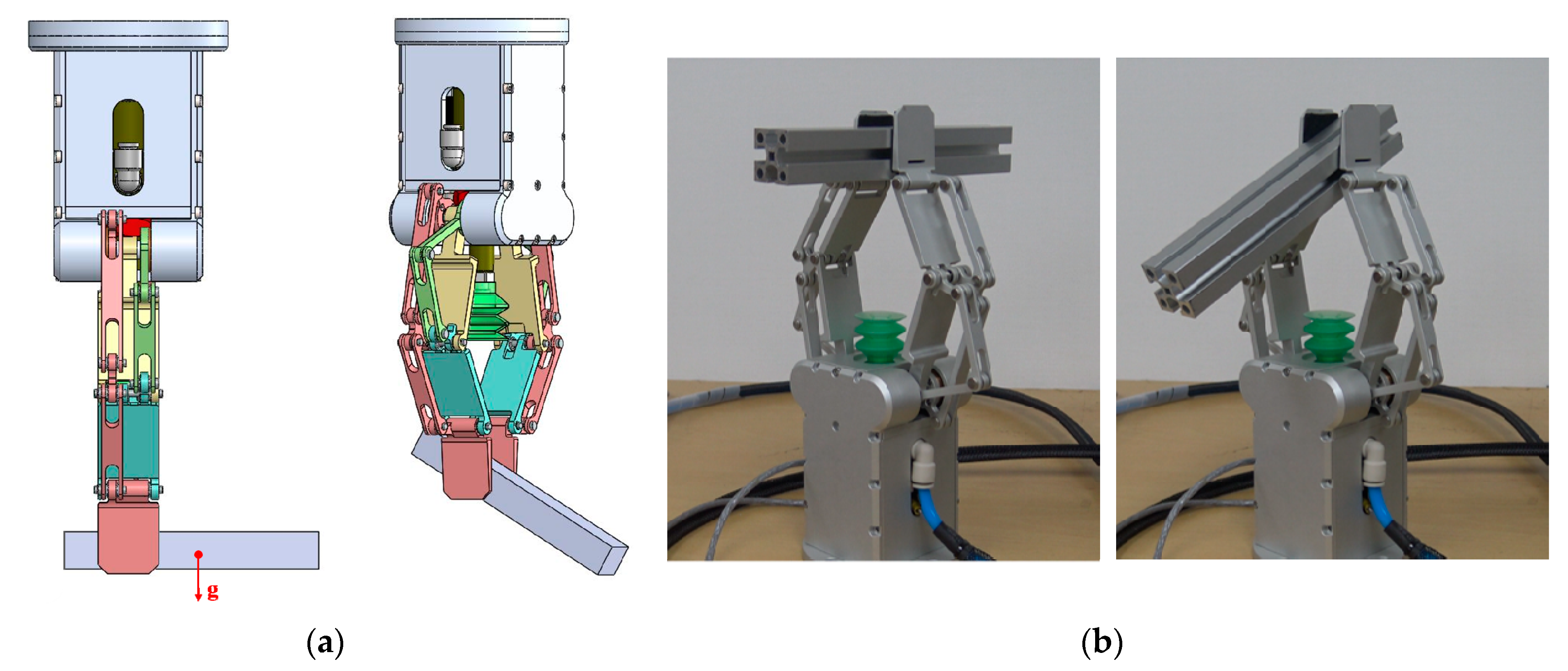
The proposed robotic finger can be used to design multi-finger robotic hands/grippers. In this work, we use the underactuated-type robotic finger to design a two-finger underactuated gripper, as shown in Figure 5. The kinematic parameters of the underactuated gripper are listed in Table 1. The two fingers of this underactuated gripper are independently operated. Furthermore, for each underactuated finger, two actuators are required to control its open-close motion and the orientation of the distal phalanx. For each motor, a worm gear is used as a non-back-drivable transmission mechanism to ensure grasping. The specifications of the actuation system, which include the motor type, controller type, and gear ratio, are listed in Table 2.
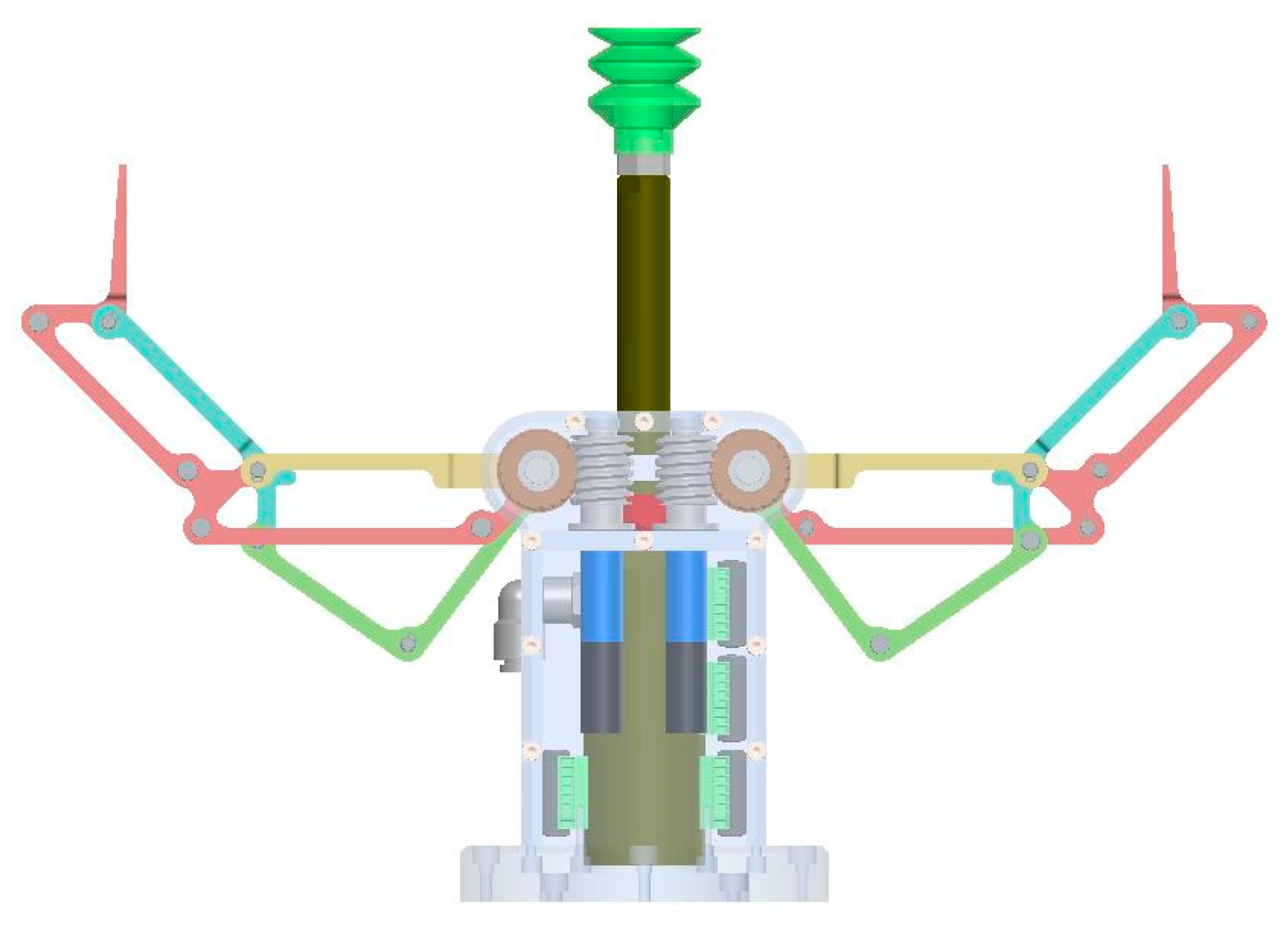
The suction-grasping system consists of an air compressor, an ejector, a filter, a vacuum cylinder, and a suction cup. The vacuum-lifting cylinder attached to the gripper palm has an 80-mm stroke. Figure 5 shows that when the two robotic fingers stay at an open configuration, suction grasping can be performed to grasp objects in a cluttered narrow environment. The system overview of the multi-function grasping system including a six-DOF commercial robot arm, is shown in Figure 6.
2.3. Comparison with One Commercialized Three-Phalanx Robotic Gripper
To demonstrate the special feature of our robotic finger. A comparison is made between our three-DOF robotic finger and the well-known three-DOF underactuated finger used in Robotiq’s three-finger adaptive gripper (licensed from [27]).
The architecture of the finger used in Robotiq’s three-finger adaptive gripper is shown in Figure 7b,c. Its design principle can be explained as follows: First, a general three-DOF shape adaptive finger, as we explained earlier, is shown in Figure 7a. This finger mechanism can be used to perform shape-adaptive grasping, with at most three contact points at the three phalanxes in sequence. However, this finger mechanism cannot be used to perform parallel grasping, as its distal phalanxes cannot be maintained to be parallel to each other. To achieve parallel grasping mode, Gosselin and Laliberté [27] developed a three-DOF underactuated finger by adding two parallelograms to the three-DOF shape-adaptive finger shown in Figure 7a. Their design is shown in Figure 7b,c. From Figure 7c, we can see that the two parallelograms are coupled to proximal and intermediate phalanxes of the shape-adaptive finger. By adding two mechanical stoppers and two springs at the bottom and top ends of the finger, parallel grasping can be achieved as shown in Figure 7b,c. However, in their design, the orientation of the distal phalanx is passively coupled with the intermediate phalanx through mechanical elements and cannot be actively controlled. Hence, except for parallel and shape-adaptive grasping, this finger design might not be appropriate for performing other challenging grasping tasks. But it has the advantage of achieving stable shape-adaptive grasping by using only one actuator to control the three phalanxes in sequence, as shown in Figure 7c.
Compared with Robotiq’s finger, our design has a simpler structure in terms of the design complexity and number of mechanical links. The orientation of the distal phalanx of our robotic finger can be controlled independently by activating link , shown in Figure 3. This feature enables the finger to perform multiple grasping tasks. Actively adjusting the orientation of the distal phalanx is also important for design a multi-finger robotic hand, which is our on-going work.
3. Grasping Modes and Grasping Strategy
This multi-function gripper is developed to grasp general objects in different working environments. It can be used to achieve multiple grasping modes, such as parallel grasping, non-parallel grasping, shape-adaptive power grasping, suction, suction-and-pinch grasping, and many other grasping tasks. In this section, we present several examples that are selected to investigate their corresponding grasping strategies. Moreover, the possibility of using this new linkage-driven gripper to perform some challenging grasping tasks is presented.
3.1. Parallel Grasping
3.1.1. Sequence Demonstration of Parallel Grasping
As explained earlier, two motors are required to control each underactuated finger. One motor is used to control the open-close motion, and the other one is used to control the orientation of the distal phalanx. When both the two fingers are simultaneously controlled to perform the open-close motion and no external contact occurs at the proximal linkages, parallel grasping can be achieved, as shown from Figure 8a–c. It is noted that to make sure that these two independent fingers can be synchronized during parallel grasping, initialization is required before performing a grasping task. Initially, we need to move the gripper to the home position where both of the two fingers are fully opened. Due to the mechanical limitation, after moving to the fully opened configuration, the fingers cannot move anymore, and the motor current will be increased rapidly. Then we use the current feedback from the motor to detect whether these two fingers move to the fully opened configurations or not. Because we can find the absolute position of each finger at the fully opened configuration from the 3D model, we can control the synchronization of the two fingers. Video attachment demonstrates how motion synchronization is achieved.
3.1.2. Analysis of Parallel Grasping Force
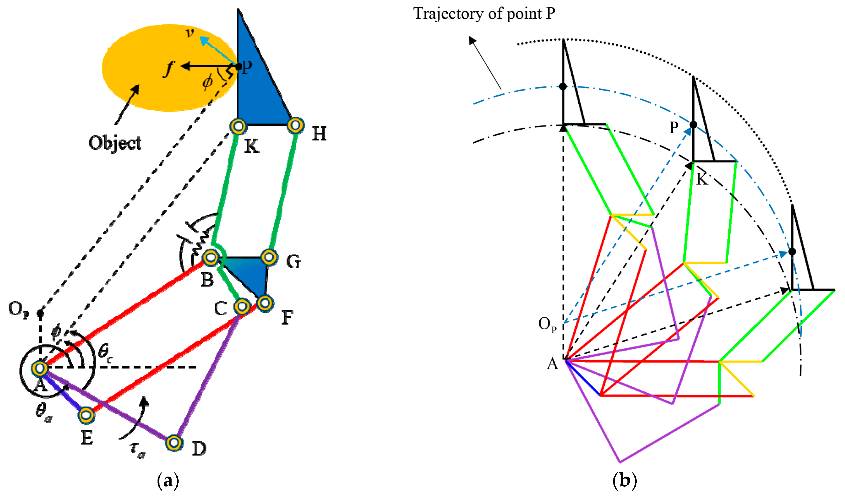
The relationship between the parallel-grasping force and actuation torque can be evaluated with the quasi-static modeling of the finger. As mentioned earlier, during the parallel-grasping sequence, the entire finger moves as a single rigid body through using one motor to control the link . The parallel grasping model is shown in Figure 9a. By equating the input and output virtual power, we have
where referring to Figure 9a, represents the contact force at contact point P during parallel grasping, represents the instantaneous velocity of the contact point P, represents the actuation torque exerted on the link used to perform the open-close motion of the finger, represents the angular velocity of the active link, i.e., and denotes the open-close angle of the active link with respect to the horizontal axis.
During the parallel-grasping sequence, the entire finger moves as a single rigid body to perform the open-close motion. Thus, point K shown in Figure 9a will follow a circular trajectory with its rotation center located at point A. Because the orientation of the distal phalanx remains constant during the open-close motion, all its points have the same instantaneous velocity. By defining a virtual parallelogram () shown in Figure 9a, we know that the contact point P follows a circular trajectory with its rotation center located at the virtual point .The motion of contact point P during parallel grasping is shown in Figure 9b. The velocity of contact point P is the same as the velocity of point K, which can be derived as
As we know, the whole finger moves as a single rigid body, we have
where is a constant value that can be found from our design.
Then we have
From Figure 9a and substituting Equations (2) and (4) into Equation (1), Equation (1) can be rewritten as
Thus, the parallel-grasping force can be obtained as
The power-transmission system consists of the motor gear head and worm-gear set. By considering the power efficiency, the relationship between the actuation torque of independent link and input motor torque can be derived as
where is the input motor torque. and are the gear ratio and efficiency of the motor gear head, respectively. and are the gear ratio and efficiency of the worm-gear set, respectively.
Moreover, the motor capacity can be determined according to the payload requirement using the above-mentioned relationship between the grasping force and input motor torque.
Furthermore, because the efficiency coefficients ( and ) shown in Equation (7) are difficult to accurately evaluate, accurately measuring the energy efficiency of the power-transmission system becomes difficult. Thus, Equation (6) can only be used to estimate the grasping force. In order to accurately control the grasping force, we need to install a force sensor at the distal phalanx.
3.2. Shape-Adaptive Grasping
During performing the open-close motion of the two fingers, when the grasped object makes contact (external forces and are applied) with the proximal phalanx, the parallel-grasping mode shown in Figure 8 will transform into shape-adaptive grasping, as shown in Figure 10. Keeping closing the finger forces the angle between the proximal and intermediate phalanxes to decrease. During this process, the torsion spring is twisted by the motor. Thus, the stiffness of the torsion spring should be designed as small as possible, but sufficiently large to prevent undesired motion due to the weight and inertia.
3.3. Combination of the Suction and Mechanical Grippers
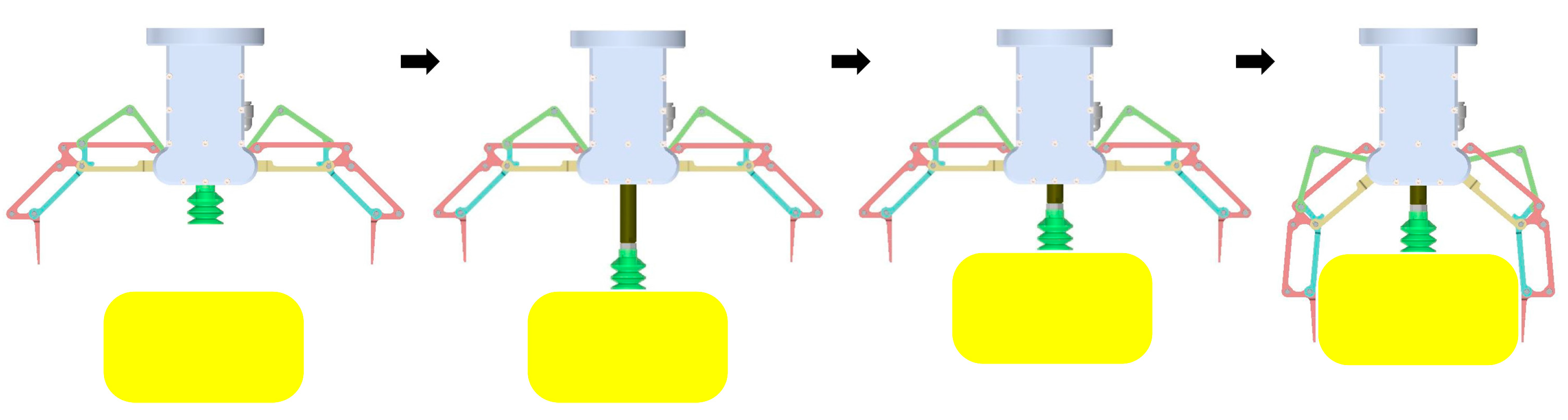
As explained earlier, conventional mechanical grippers/hands provide the advantage of achieving stable grasping in open space. Meanwhile, applying them in a cluttered narrow space is difficult because multiple physical contacts might occur. In comparison, the suction grasper offers the advantage of grasping objects in a cluttered narrow environment. Meanwhile, pure suction grasping is generally unstable because the suction cup is too soft to maintain the configuration of the grasped object. Hence, combining the mechanical gripper/hand with the suction grasper is an efficient method to grasp general objects in different types of working environments. The grasping sequence of this multi-function gripper is shown in Figure 11.
3.4. Contact-Based Grasping
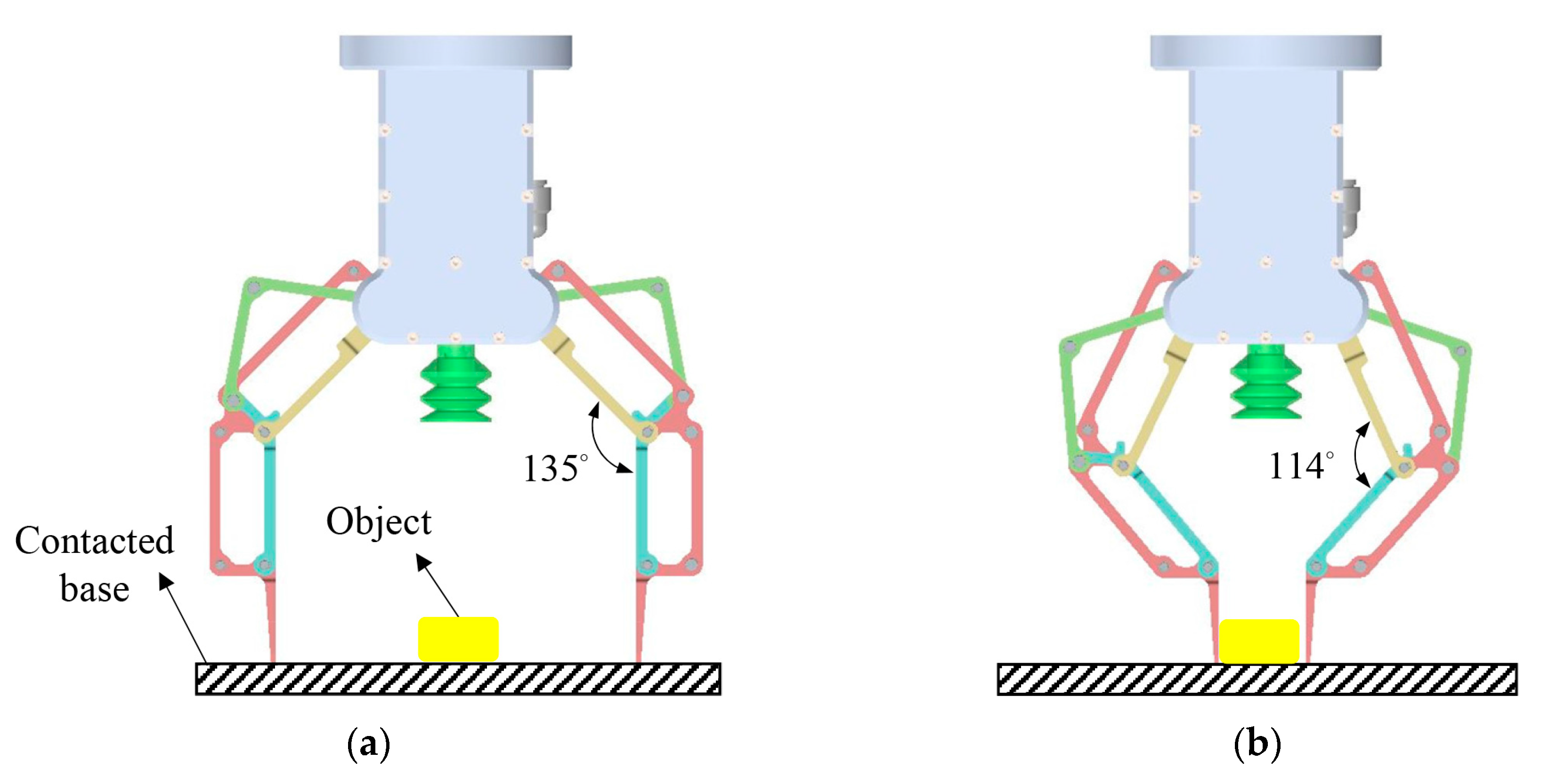
In addition to the above-mentioned three types of grasping modes, this gripper can be used to perform some other challenging grasping tasks. One special feature of this linkage-driven gripper is that the orientation of the distal phalanx of each finger can be actively controlled and decoupled from the open-close motion of the finger. Thus, during the parallel-grasping sequence, the distal phalanx can be maintained at a desired orientation even when it contacts with the external environment, as shown in Figure 12. This grasping mode is quite useful when we plan to grasp relatively thin objects lying on a flat surface. Many grippers/hands fail to grasp objects in such a manner because when they make contact with the supporting base, the orientation of the distal phalanx of their robotic finger will change because of the coupled structure. To achieve grasping using other grippers/hands, a good calibration algorithm and a highly accurate computer-vision system are generally required to grasp such objects without making any contact with the environment.
3.5. Grasping Thin Objects via Scooping
Because the two fingers of the underactuated gripper are independently controlled and the orientation of the distal phalanx of each finger can be actively adjusted, using our gripper to pick up thin objects lying on a flat surface via scooping becomes possible [28]. We note that to ensure that the fingertip can scoop in the space between the object to be grasped and the supporting base, the fingernail for insertion should be specially designed to be frictionless and sufficiently sharp. The following experiment demonstrates the whole grasping sequence.
4. Experimental Evaluation and Discussion
To validate the design concept of this multi-function gripper, an aluminum prototype is manufactured to test its performance in the real world. A commercially available six-DOF robot arm is integrated into the experimental system. Different types of grasping modes, including parallel grasping, shape-adaptive grasping, combination of the suction and mechanical grippers, contact-based grasping, and grasping thin objects lying on a flat surface via scooping, are experimentally verified.
4.1. Independent Motion Demonstration
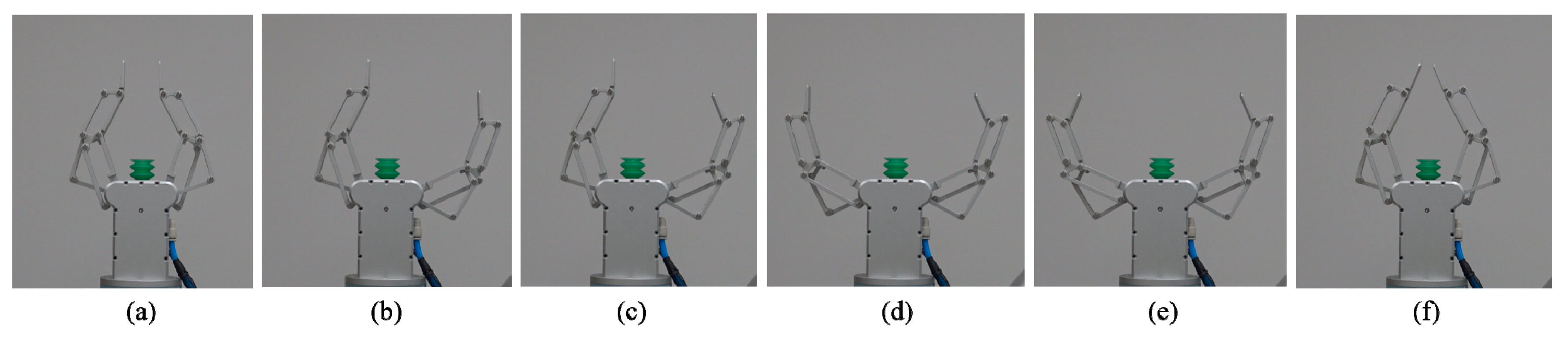
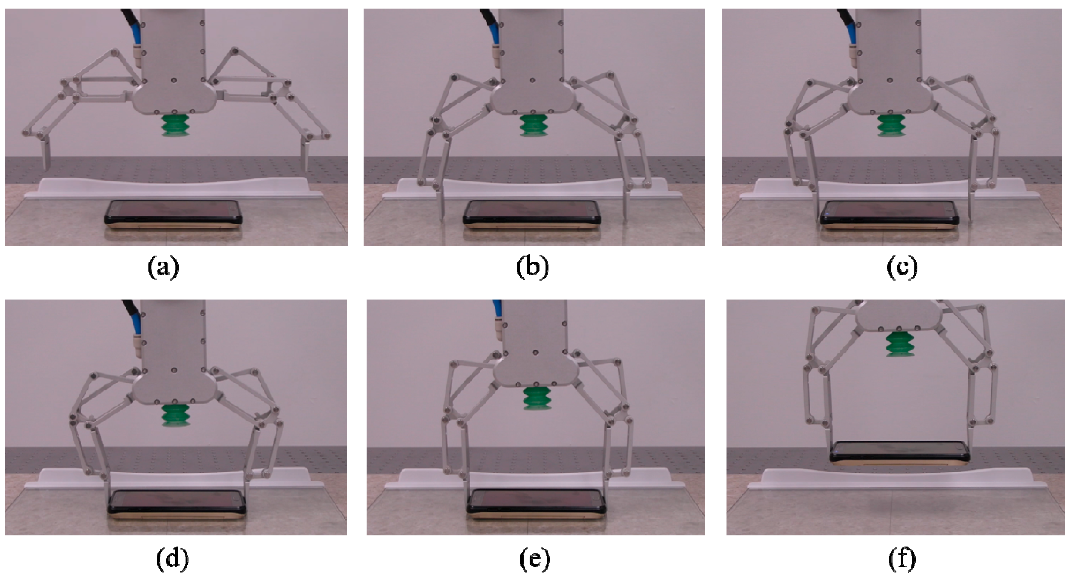
As mentioned earlier, this linkage-driven gripper has two fingers that can be controlled independently. Furthermore, each finger has two independent motions, i.e., the open-close motion of the finger and distal-phalanx orientation adjustment. Figure 13 shows a demonstration of the four independent motions. From Figure 13a,b, the right finger performs the open-close motion. From Figure 13b,c, the distal-phalanx orientation of the right finger is adjusted. From Figure 13c,d, the left finger performs the open-close motion. From Figure 13d,e, the distal-phalanx orientation of the left finger is adjusted. Finally, from Figure 13e,f, the two fingers are closed simultaneously.
4.2. Suction Experiments
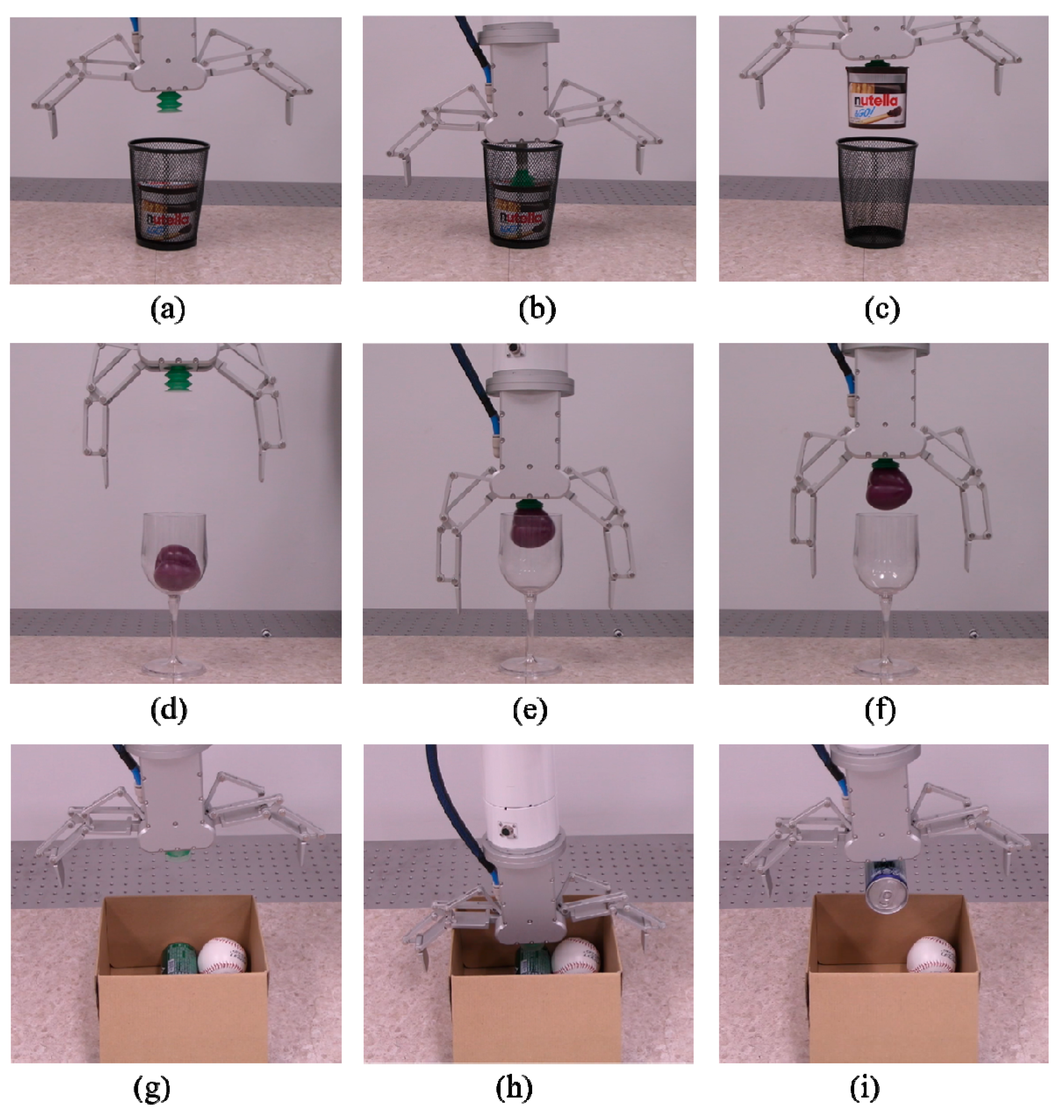
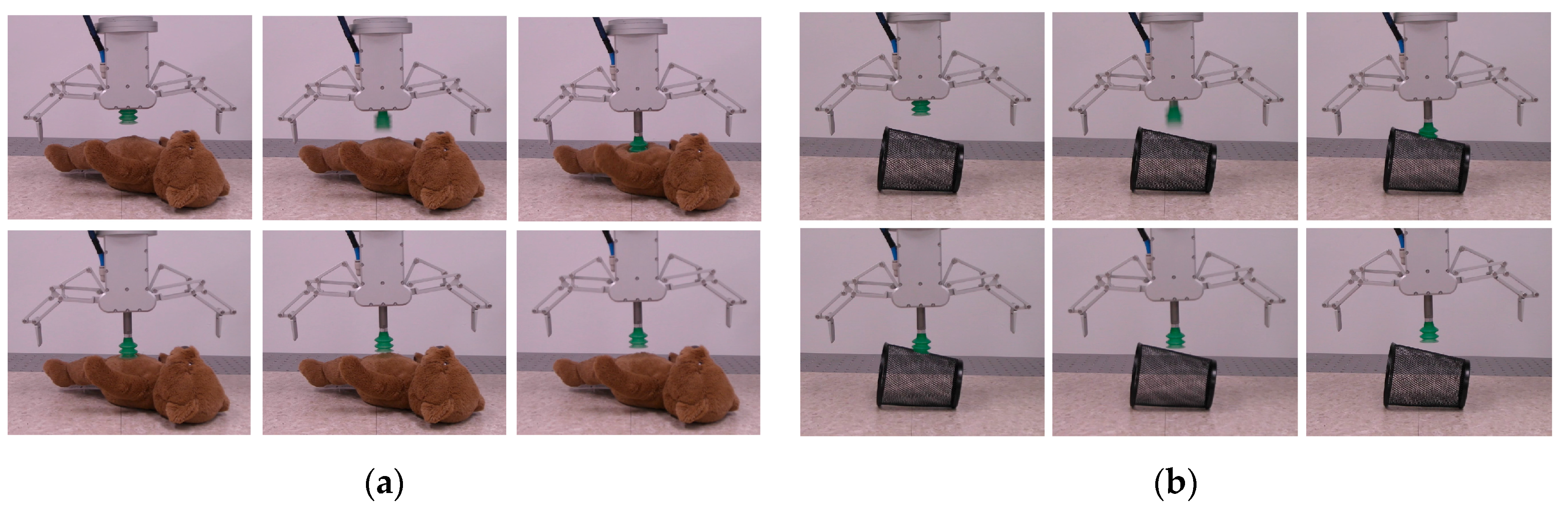
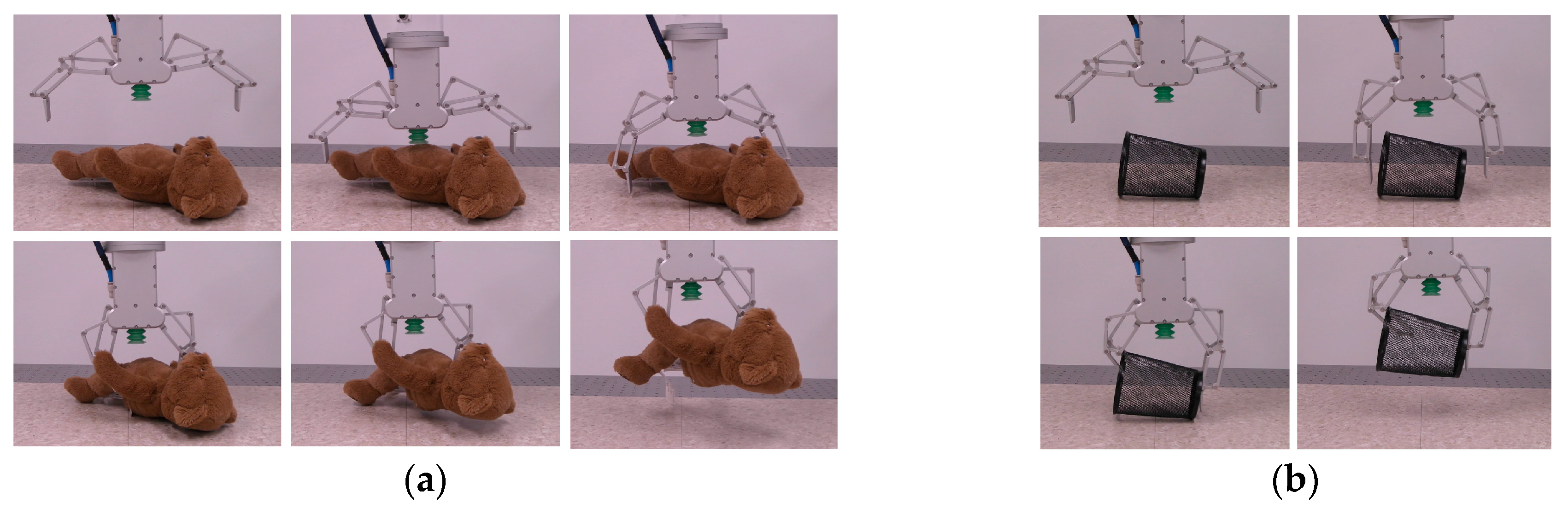
As mentioned earlier, suction grasping offers the advantage of grasping objects in a cluttered narrow environment. Figure 14 shows some examples of successful suction grasping, which are difficult to achieve with the mechanical gripper. However, using the suction gripper to grasp objects made of fabric materials or objects with multiple holes is difficult. Figure 15 shows this condition.
4.3. Linkage-Driven Gripper Experiments
Even though mechanical grippers have difficulty in grasping objects in a cluttered narrow space, using them to stably grasp objects in open space is simple. For the objects shown in Figure 15, using the suction gripper to grasp them is difficult. In comparison, using mechanical grippers to grasp such objects is simple, as shown in Figure 16.
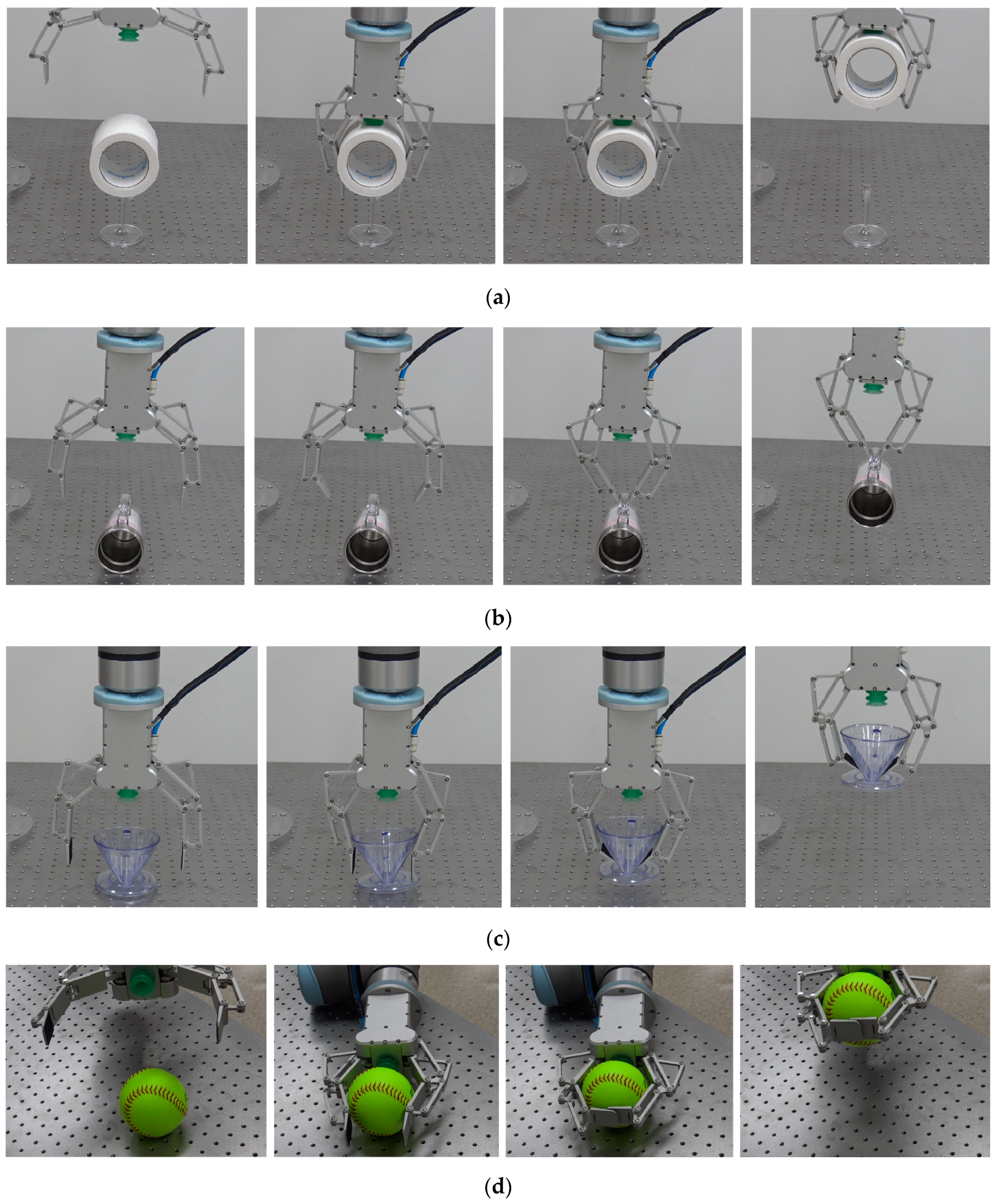
Moreover, Figure 17 shows how the pinch motion of the distal phalanx of the robotic finger is used to grasp different objects in different scenarios. The object shown in Figure 17a lies above the supporting base, i.e., there exists a spare space between the object and the base. Actively controlled pinch motion allows the finger to scoop the object up from the bottom side. Figure 17b shows using the closed distal phalanx to grasp a cup having a lifting ear. This kind of grasping mode is similar to caging [29,30]. Figure 17c shows how to grasp objects with a cone shape. Figure 17d shows one example of grasping though making contacts at both phalanxes and palm.
4.4. Combination of the Suction and Mechanical Grippers
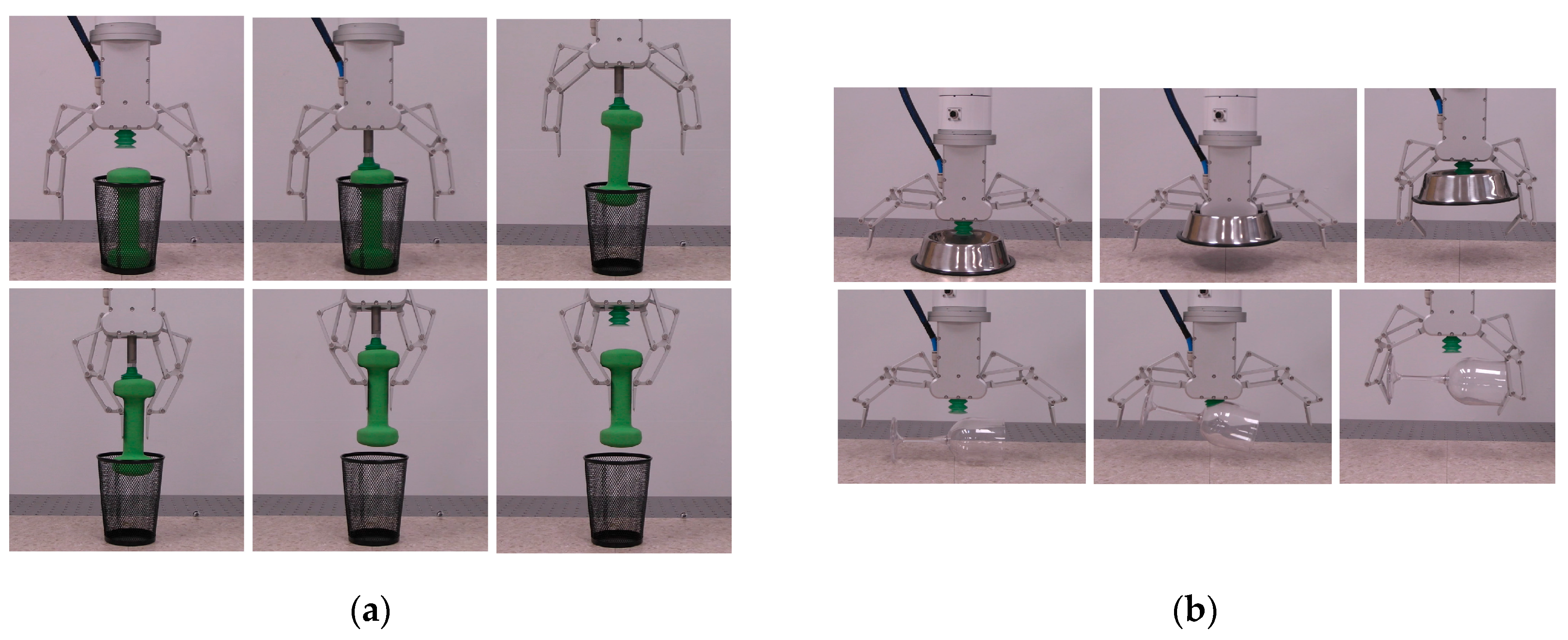
The suction gripper cannot stably grasp heavy objects that lie in a narrow space. In this case, the combination of suction and linkage-driven grippers will be an efficient method for achieving stable grasping. Figure 18a shows an example of grasping a 1.35 kg dumbbell from a narrow space. Figure 18b shows how the multi-function gripper is used to grasp an object with a cone shape and that with an irregular shape.
4.5. Environment Contact-Based Grasping
Figure 19 shows contact-based grasping. We note that during physical contact with the supporting base, the torsion spring is twisted. Thus, after the contact-based grasping is finished and the six-DOF robot arm is lifting the gripper up, the torsion spring will be released. Because the proximal and intermediate phalanx are passively coupled by the torsion spring, the distance between two robotic fingers might increase if we don’t control the gripper actively. Hence, to prevent the objects from falling, we need to actively control the closing speed of the gripper to ensure that the closing speed is faster than the finger-opening speed caused by the lifting of the six-DOF robot arm.
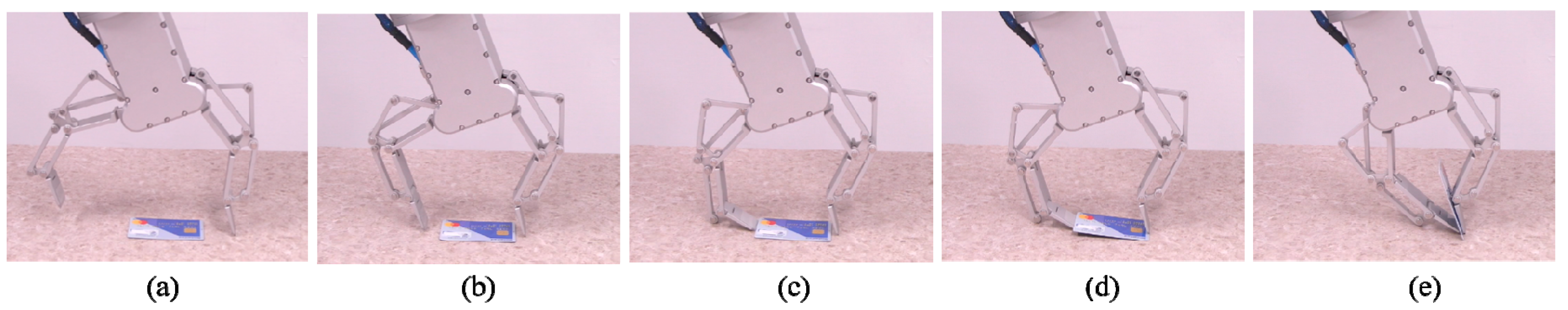
4.6. Grasping Thin Objects via Scooping
Figure 20 shows an example of grasping thin objects lying on a flat surface by scooping. We note that the fingernail of the left robotic finger used for scooping needs to be sufficiently sharp and frictionless to scoop at the bottom side of the object. Moreover, the object to be grasped should not be too rigid, and an appropriate control algorithm is required for a stable and robust scooping task. This example only provides a simple demonstration of the possibility of performing a scooping task using our proposed gripper.
4.7. Discussion
Two-finger grippers have been extensively used in industrial application and automated assembly because 60 to 70% of human’s grasping of objects of cylindrical, parallelepiped, and pyramidal shapes is performed with only two fingers, and two-finger grippers are generally cheaper and easier to use as compared with multi-finger grippers/hands [31,32]. Our prototype gripper was manufactured using aluminum alloy. Because ball bearings are used at all joints, friction in the joints can be considered to be negligible.
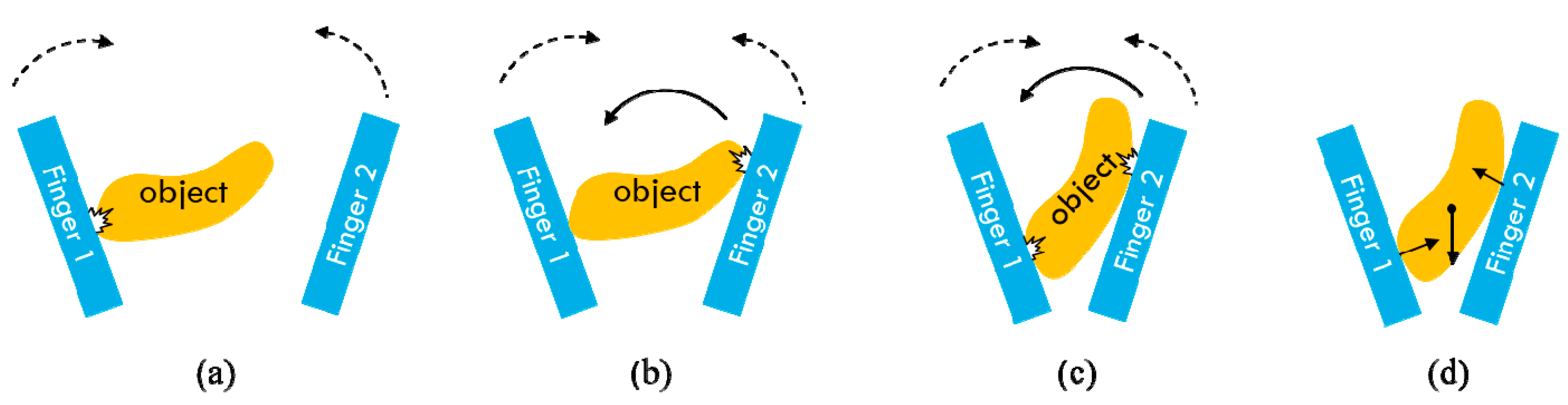
Different phases of two-finger grasping with only two contact points are shown in Figure 21. The two fingers will make contact with the object in sequence. From Figure 21b,c, we can see that the object is dragged by the finger during continuous closure movement. Figure 21d demonstrates the phase where a static grasp is achieved. In order to model these phases, the planar grasp model [33] for a two-finger gripper is shown in Figure 22. The static equilibrium condition of a planar grasp can be expressed in the directions of the contact and squeezing line as follows
where and are the grasping forces at contact points A and B. and are the friction coefficients at contact points A and B. and represent the distances of contact points A and B. represents the distance of the gravity center. represents the weight vector of the objects. It is orientated with an angle with respect to the squeezing line and an angle with respect to the perpendicular axis to the y–z plane. and represents the acceleration components of the gravity center point. is an external torque acting on the object and the inertia effect due to the manipulator movement is also included. This grasp model describes all situations of a two-finger grasping as pointed out by Ceccarelli [34].
From Figure 21 and Figure 22, it can be found that the static equilibrium might be difficult to achieve by using only two grasping forces, especially in the case that the two fingertips are not parallel to each other. From Equations (8) to (10), we can see that with only two grasping forces (two unknowns), it might be difficult to ensure that all those three equations hold. As mentioned earlier, both parallel grasping (two fingertips are parallel to each other) and non-parallel grasping (through adjusting the orientation of the distal phalanx) can be realized by using our two-finger gripper.
As far as the parallel grasping is concerned, the parallel grasping force depends on friction forces at the fingertip [35,36]. The parallel grasping can be achieved by using the outer or interior surface parallelepiped of the fingertip. For cylindrical objects or those with parallel surfaces to both fingers, the parallel or opposed grasping force can be produced. If the directions of these forces coincide and friction forces generated are big enough, the parallel grasping generally can be achieved stably. The friction force depends on the nature of two surfaces in contact. For example, the sliding contact and rolling contact would have different friction forces. And the friction coefficient between the contact surface and the object can be increased by adding a friction pad at the fingertip. Furthermore, because the two-finger parallel grasping has only two contact areas/points, grasping points would also influence the stability of the two-finger parallel grasping. For example, it might be unstable to grasp a relatively long object by selecting the corresponding grasp contact points shown in Figure 23a. This is because the gravity center of the object is far from the grasping zone. The gravity force will generate some rotation torque, which is a leading cause of the unstable two-finger parallel grasping. Experiments of grasping the same object at different contact points were performed as shown in Figure 23b. We note that the grasping motor was actuated by using almost the same current in these two experiments. The left panel shown in Figure 23b demonstrates the success of a stable grasping by selecting the grasping points/area near the gravity center. The right panel shown in Figure 24b demonstrates one case of unstable grasping.
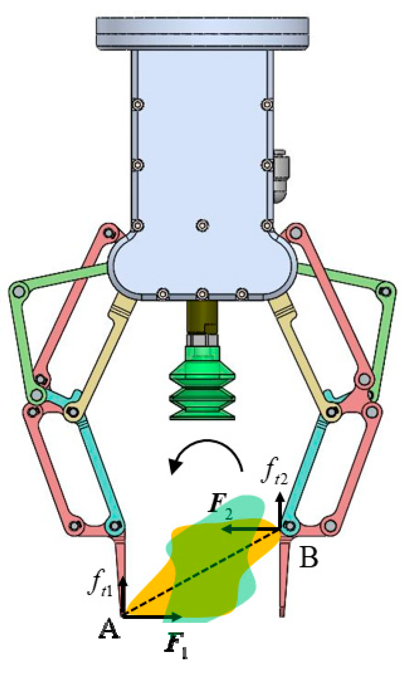
As far as the objects with irregular shapes are concerned, if the two contact points are not well selected, the static force equilibrium might not be achieved. One example is shown in Figure 24, where the two contact points A and B are relatively far from each other. During applying the contact forces, the configuration of the object might be changed (Initial configuration of the object is indicated by yellow color; the new configuration is indicated by transparent green color) because the two contact forces do not coincide, a winding moment will be produced on the object. After continually applying the grasping force, it is not sure whether the static equilibrium between two fingers can be achieved or not. In this case, a multi-contact grasping generally is required for achieving stable grasping. For certain objects to be grasped, the grasping mode and grasp contact points should be carefully selected. It is also possible to increase the grasping stability by adding an appropriate compliant structure to the fingertip because the compliance increases the ability of a gripper to conform to the shape of the object being grasped, and also increases the area of the contact patches, increasing the grasp wrench space [37].
5. Conclusions
To grasp general objects in different working environments, a multi-function grasping system is developed in this study. A new two-finger underactuated gripper is proposed and integrated to a suction-grasping system. The performance of this multi-function gripper is evaluated through both simulations and real-world experiments. We verify that this multi-function gripper can be used to perform many types of grasping tasks.
Two-finger grasping with only two contact points might not be stable in some grasping scenarios. To achieve a stable grasping, the grasping modes and contact points should be carefully selected by taking the characteristics of the object, such as the size and shape, the weight and location of the gravity center, and the friction knowledge of the surface, into consideration.
For scooping and picking up thin objects lying on flat surfaces, our future work will focus on design special fingernails and appropriate motion/force control algorithms to increase the success rate of grasping. Currently, we are using current feedback from the motor to detect the contact and grasping state. In the future, tactile sensors will be added to the gripper to detect the contact and grasping forces. Moreover, we will use the new three-DOF robotic finger to develop a multi-finger robotic hand.
Author Contributions
Conceptualization: L.K., J.-T.S., and B.-J.Y.; visualization: L.K. and J.-T.S.; software: L.K.; writing—original draft preparation: L.K.; writing—review and editing: L.K.; supervision: B.-J.Y.; experimentation: L.K., S.-H.K., J.-T.S., and W.-J.K.
Funding
This research was funded by the Technology Innovation Program (or Industrial Strategic Technology Development Program) (Grant Number 20001856, Development of Robotic Work Control Technology Capable of Grasping and Manipulating Various Objects in Everyday Life Environment Based on Multimodal Recognition and Using Tools) funded by the Ministry of Trade, Industry and Energy (MOTIE, Sejong City, Korea), and performed by the ICT-based Medical Robotic Systems Team of Hanyang University, Department of Electronic Systems Engineering was supported by the BK21 Plus Program funded by the National Research Foundation of Korea (NRF). The APC was funded by Grant Number 20001856.
Conflicts of Interest
The authors declare no conflict of interest.
References
- Grebenstein, M.; Albu-Schäffer, A.; Bahls, T.; Chalon, M.; Eiberger, O.; Friedl, W.; Gruber, R.; Haddadin, S.; Hagn, U.; Haslinger, R.; et al. The DLR hand arm system. In Proceedings of the 2011 IEEE International Conference on Robotics and Automation, Shanghai, China, 9–13 May 2011; pp. 3175–3182. [Google Scholar]
- Shadow Dexterous Hand. Design of a Dextrous Hand for Advanced CLAWAR Applications. Available online: http://www.shadowrobot.com/downloads/dextrous_hand_final.pdf (accessed on 31 July 2019).
- Bridgwater, L.B.; Ihrke, C.; Diftler, M.A.; Abdallah, M.E.; Radford, N.A.; Rogers, J.; Yayathi, S.; Askew, R.S.; Linn, D.M. The robonaut 2 hand-designed to do work with tools. In Proceedings of the 2012 IEEE International Conference on Robotics and Automation, Vilamoura, Algarve, Portugal, 7–12 October 2012; pp. 3425–3430. [Google Scholar]
- Yao, S.; Ceccarelli, M.; Carbone, G.; Dong, Z. Grasp configuration planning for a low-cost and easy-operation underactuated three-fingered robot hand. Mech. Mach. Theory 2018, 129, 51–69. [Google Scholar] [CrossRef]
- Birglen, L.; Laliberté, T.; Gosselin, C.M. Underactuated Robotic Hands; Springer: Berlin Heidelberg, Germany, 2007; Volume 40. [Google Scholar]
- Mitsui, K.; Ozawa, R.; Kou, T. An under-actuated robotic hand for multiple grasps. In Proceedings of the 2013 IEEE/RSJ International Conference on Intelligent Robots and Systems, Tokyo, Japan, 3–7 November 2013; pp. 5475–5480. [Google Scholar]
- Yamaguchi, K.; Hirata, Y.; Kosuge, K. Underactuated robot hand for dual-arm manipulation. In Proceedings of the 2015 IEEE/RSJ International Conference on Intelligent Robots and Systems, Hamburg, Germany, 28 September–2 October 2015; pp. 2937–2942. [Google Scholar]
- Odhner, L.U.; Ma, R.R.; Dollar, A.M. Precision grasping and manipulation of small objects from flat surfaces using underactuated fingers. In Proceedings of the 2012 IEEE International Conference on Robotics and Automation, Saint Paul, MN, USA, 14–18 May 2012; pp. 2830–2835. [Google Scholar]
- Ozawa, R.; Hashirii, K.; Kobayashi, H. Design and control of underactuated tendon-driven mechanisms. In Proceedings of the 2009 IEEE International Conference on Robotics and Automation, Kobe, Japan, 12–17 May 2009; pp. 1522–1527. [Google Scholar]
- Ozawa, R.; Mishima, Y.; Hirano, Y. Design of a Transmission with Gear Trains for Underactuated Mechanisms. IEEE Trans. Robot. 2016, 32, 1399–1407. [Google Scholar] [CrossRef]
- Birglen, L.; Gosselin, C.M. Kinetostatic analysis of underactuated fingers. IEEE Trans. Robot. Autom. 2004, 20, 211–221. [Google Scholar] [CrossRef]
- Rakić, M. Multifingered robot hand with selfadaptability. Robot. Comput. Integr. Manuf. 1989, 5, 269–276. [Google Scholar] [CrossRef]
- Birglen, L.; Gosselin, C.M. Geometric Design of Three-Phalanx Underactuated Fingers. J. Mech. Des. 2005, 128, 356–364. [Google Scholar] [CrossRef]
- Catalano, M.G.; Grioli, G.; Farnioli, E.; Serio, A.; Piazza, C.; Bicchi, A. Adaptive synergies for the design and control of the Pisa/IIT SoftHand. Int. J. Robot. Res. 2014, 33, 768–782. [Google Scholar] [CrossRef] [Green Version]
- Wu, L.; Carbone, G.; Ceccarelli, M. Designing an underactuated mechanism for a 1 active DOF finger operation. Mech. Mach. Theory 2009, 44, 336–348. [Google Scholar] [CrossRef]
- Zhang, W.; Che, D.; Liu, H.; Ma, X.; Chen, Q.; Du, D.; Sun, Z. Super under-actuated multi-fingered mechanical hand with modular self-adaptive gear-rack mechanism. Ind. Robot Int. J. Robot. Res. Appl. 2009, 36, 255–262. [Google Scholar] [CrossRef]
- Yoon, D.; Choi, Y. Underactuated Finger Mechanism Using Contractible Slider-Cranks and Stackable Four-Bar Linkages. IEEE/ASME Trans. Mechatron. 2017, 22, 2046–2057. [Google Scholar] [CrossRef]
- The Barrett Hand. The Barrett Hand. Available online: https://www.barrett.com/about-barretthand (accessed on 10 September 2019).
- ReFlex Hand. Available online: https://www.labs.righthandrobotics.com/reflexhand (accessed on 21 September 2019).
- ROBOTIQ. 2F-85 and 2F-140 Grippers. Available online: https://robotiq.com/products/2f85-140-adaptive-robot-gripper (accessed on 17 July 2019).
- ROBOTIQ. 3-Finger Adaptive Robot Gripper. Available online: https://robotiq.com/products/3-finger-adaptive-robot-gripper (accessed on 17 July 2019).
- Correll, N.; Bekris, K.E.; Berenson, D.; Brock, O.; Causo, A.; Hauser, K.; Okada, K.; Rodriguez, A.; Romano, J.M.; Wurman, P.R. Lessons from the amazon picking challenge. arXiv 2016, arXiv:1601.05484. [Google Scholar]
- Yu, K.T.; Fazeli, N.; Chavan-Dafle, N.; Taylor, O.; Donlon, E.; Lankenau, G.D.; Rodriguez, A. A summary of team mit’s approach to the amazon picking challenge. arXiv 2016, arXiv:1604.03639 2016. [Google Scholar]
- Yamaguchi, K.; Hirata, Y.; Kosuge, K. Development of robot hand with suction mechanism for robust and dexterous grasping. In Proceedings of the 2013 IEEE/RSJ International Conference on Intelligent Robots and Systems, Tokyo, Japan, 3–7 November 2013; pp. 5500–5505. [Google Scholar]
- Hasegawa, S.; Wada, K.; Niitani, Y.; Okada, K.; Inaba, M. A three-fingered hand with a suction gripping system for picking various objects in cluttered narrow space. In Proceedings of the 2017 IEEE/RSJ International Conference on Intelligent Robots and Systems, Vancouver, BC, Canada, 24–28 September 2017; pp. 1164–1171. [Google Scholar]
- RightPick. Available online: https://www.righthandrobotics.com/ (accessed on 14 October 2019).
- Gosselin, C.M.; Laliberté, T. Underactuated Mechanical Finger with Return Actuation. U.S. Patent No. 5,762,390, 9 June 1998. [Google Scholar]
- Babin, V.; Gosselin, C. Picking, grasping, or scooping small objects lying on flat surfaces: A design approach. Int. J. Robot. Res. 2018, 37, 1484–1499. [Google Scholar] [CrossRef]
- Rimon, E.; Blake, A. Caging Planar Bodies by One-Parameter Two-Fingered Gripping Systems. Int. J. Robot. Res. 1999, 18, 299–318. [Google Scholar] [CrossRef]
- Makita, S.; Wan, W. A survey of robotic caging and its applications. Adv. Robot. 2017, 31, 1071–1085. [Google Scholar] [CrossRef]
- Ceccarelli, M.; Gradini, G. Robot’s gripper mechanism: Classification and optimization. Autom. Robot. Tech. 1992, 1–20. [Google Scholar]
- Pham, D.T.; Heginbotham, W.B. Robot Grippers; IFS Publications Ltd.: Bedford, UK, 1986. [Google Scholar]
- Saramago, S.F.P.; Ceccarelli, M. An optimum robot path planning with payload constraints. Robotica 2002, 20, 395–404. [Google Scholar] [CrossRef]
- Ceccarelli, M. Design problems for industrial robot two-finger grippers. In Proceedings of the the 3rd International Workshop on Robotics in Alpe-Adria, Bled, Slovenia, 7–9 July 1994; pp. 117–120. [Google Scholar]
- Ceccarelli, M. Fundamentals of Mechanics of Robotic Manipulation; Springer Science & Business Media: Berlin Heidelberg, Germany, 2004; Volume 27. [Google Scholar]
- Carbone, G. Grasping in Robotics; Springer: Berlin Heidelberg, Germany, 2012; Volume 10. [Google Scholar]
- Chang, C.M.; Gerez, L.; Elangovan, N.; Zisimatos, A.; Liarokapis, M. On Alternative Uses of Structural Compliance for the Development of Adaptive Robot Grippers and Hands. Front. Neurorobot. 2019, 13. [Google Scholar] [CrossRef] [Green Version]
Figure 1.
The closing sequence of a two-phalanx underactuated robotic finger.

Figure 2.
The closing sequence of a three-phalanx robotic finger.

Figure 3.
(a) Architecture of the three-DOF (degrees of freedom) linkage-driven robotic finger. (b) Using torsion spring and mechanical stopper to realize the underactuated finger.
Figure 3.
(a) Architecture of the three-DOF (degrees of freedom) linkage-driven robotic finger. (b) Using torsion spring and mechanical stopper to realize the underactuated finger.

Figure 4.
Grasping sequence of the underactuated finger. (a) Parallel grasping. (b) Shape-adaptive grasping.
Figure 4.
Grasping sequence of the underactuated finger. (a) Parallel grasping. (b) Shape-adaptive grasping.

Figure 5.
Two-finger underactuated gripper + suction mechanism.

Figure 6.
System overview of the multi-function grasping system.

Figure 7.
(a) A three-DOF shape adaptive finger. (b,c): Three-DOF underactuated finger proposed by Gosselin and Laliberté [27]. (b) Parallel precision grasping. (c) Shape-adaptive grasping.
Figure 7.
(a) A three-DOF shape adaptive finger. (b,c): Three-DOF underactuated finger proposed by Gosselin and Laliberté [27]. (b) Parallel precision grasping. (c) Shape-adaptive grasping.

Figure 8.
Demonstration of parallel grasping.

Figure 9.
(a) Parallel-grasping model. (b) Trajectory of contact point P.

Figure 10.
Demonstration of shape-adaptive grasping. (a) State when objects start making contact with thproximal phalanxes. (b) State when the shape-adaptive grasping is achieved.
Figure 10.
Demonstration of shape-adaptive grasping. (a) State when objects start making contact with thproximal phalanxes. (b) State when the shape-adaptive grasping is achieved.

Figure 11.
Grasping-sequence demonstration of the multi-function gripper.

Figure 12.
Parallel grasping during contact with the environment. (a) State when the gripper starts making contact with the supported surface. (b) State when the contact-based parallel grasping is done without lifting up.
Figure 12.
Parallel grasping during contact with the environment. (a) State when the gripper starts making contact with the supported surface. (b) State when the contact-based parallel grasping is done without lifting up.

Figure 13.
Demonstration of the independent motions of this linkage-driven gripper.

Figure 14.
Using a suction gripper to grasp objects in a cluttered narrow environment. (a) Grasp an object from the mesh pen/pencil cup holder. (b) Grasp a fruit from the wine glass. (c) Grasp an object surrounded by other objects from the paper box.
Figure 14.
Using a suction gripper to grasp objects in a cluttered narrow environment. (a) Grasp an object from the mesh pen/pencil cup holder. (b) Grasp a fruit from the wine glass. (c) Grasp an object surrounded by other objects from the paper box.

Figure 15.
The suction gripper fails to grasp certain objects. (a) Bear toy. (b) Mesh pen/pencil cup holder.
Figure 15.
The suction gripper fails to grasp certain objects. (a) Bear toy. (b) Mesh pen/pencil cup holder.

Figure 16.
Two-finger underactuated gripper succeeding in grasping certain objects that are difficult for the suction gripper to grasp. (a) Bear toy. (b) Mesh pen/pencil cup holder.
Figure 16.
Two-finger underactuated gripper succeeding in grasping certain objects that are difficult for the suction gripper to grasp. (a) Bear toy. (b) Mesh pen/pencil cup holder.

Figure 17.
Examples of grasping by using the pinch motion of distal phalanx. (a) Grasping a roll of toilet paper lying above a supporting base. (b) Grasping a cup through caging. (c) Grasping a cup with an irregular shape. (d) Grasping a baseball.
Figure 17.
Examples of grasping by using the pinch motion of distal phalanx. (a) Grasping a roll of toilet paper lying above a supporting base. (b) Grasping a cup through caging. (c) Grasping a cup with an irregular shape. (d) Grasping a baseball.

Figure 18.
Combination of the suction and mechanical grippers. (a) Grasping a heavy object from a narrow space. (b) Grasping objects with certain shapes that are difficult to directly grasp by the mechanical gripper.
Figure 18.
Combination of the suction and mechanical grippers. (a) Grasping a heavy object from a narrow space. (b) Grasping objects with certain shapes that are difficult to directly grasp by the mechanical gripper.

Figure 19.
Example of environment contact-based grasping.

Figure 20.
Example of scooping and picking up thin objects lying on a flat surface.

Figure 21.
Different phases of grasping objects. (a) Initial impact. (b) Second impact. (c) Applying grasping force. (d) Static equilibrium.
Figure 21.
Different phases of grasping objects. (a) Initial impact. (b) Second impact. (c) Applying grasping force. (d) Static equilibrium.

Figure 22.
Planar grasp model of a two-finger gripper.

Figure 23.
Instable parallel grasping of the two-finger underactuated gripper. (a) Demonstration of the instable grasping due to unsuitable contact points. (b) Experimental verification.
Figure 23.
Instable parallel grasping of the two-finger underactuated gripper. (a) Demonstration of the instable grasping due to unsuitable contact points. (b) Experimental verification.

Figure 24.
Instable parallel grasping of irregular objects.


Table 1.
Kinematic parameters 1 of the underactuated gripper.
| Length (mm) | Length (mm) | Angle (Deg) |
|---|---|---|
(constrained by the stopper) | ||
1 Referring to Figure 3a.
Table 2.
Specification of the actuation system.
| Motor 1 | Motor 2 | Motor 3 | Motor 4 | |
|---|---|---|---|---|
| (FAULHABER) Motor type | BLDC 1226S012B | BLDC 1226S012B | BLDC 1226S012B | BLDC 1226S012B |
| Gear head | 256:1 | 256:1 | 256:1 | 256:1 |
| Worm gear | 20:1 | 20:1 | 20:1 | 20:1 |
| Rated torque | 1.97 mNm | 1.97 mNm | 1.97 mNm | 1.97 mNm |
| Controller type | MCBL 3002S | MCBL 3002S | MCBL 3002S | MCBL 3002S |
© 2019 by the authors. Licensee MDPI, Basel, Switzerland. This article is an open access article distributed under the terms and conditions of the Creative Commons Attribution (CC BY) license (http://creativecommons.org/licenses/by/4.0/).
Share and Cite
MDPI and ACS Style
Kang, L.; Seo, J.-T.; Kim, S.-H.; Kim, W.-J.; Yi, B.-J. Design and Implementation of a Multi-Function Gripper for Grasping General Objects. Appl. Sci. 2019, 9, 5266. https://doi.org/10.3390/app9245266
AMA Style
Kang L, Seo J-T, Kim S-H, Kim W-J, Yi B-J. Design and Implementation of a Multi-Function Gripper for Grasping General Objects. Applied Sciences. 2019; 9(24):5266. https://doi.org/10.3390/app9245266
Chicago/Turabian StyleKang, Long, Jong-Tae Seo, Sang-Hwa Kim, Wan-Ju Kim, and Byung-Ju Yi. 2019. "Design and Implementation of a Multi-Function Gripper for Grasping General Objects" Applied Sciences 9, no. 24: 5266. https://doi.org/10.3390/app9245266
Note that from the first issue of 2016, this journal uses article numbers instead of page numbers. See further details here.