Scattering or Pushing for Object Singulation in Cluttered Environment: Case Study with Soma Cube


 , ,
, ,  and
and
Abstract
:Featured Application
Abstract
1. Introduction
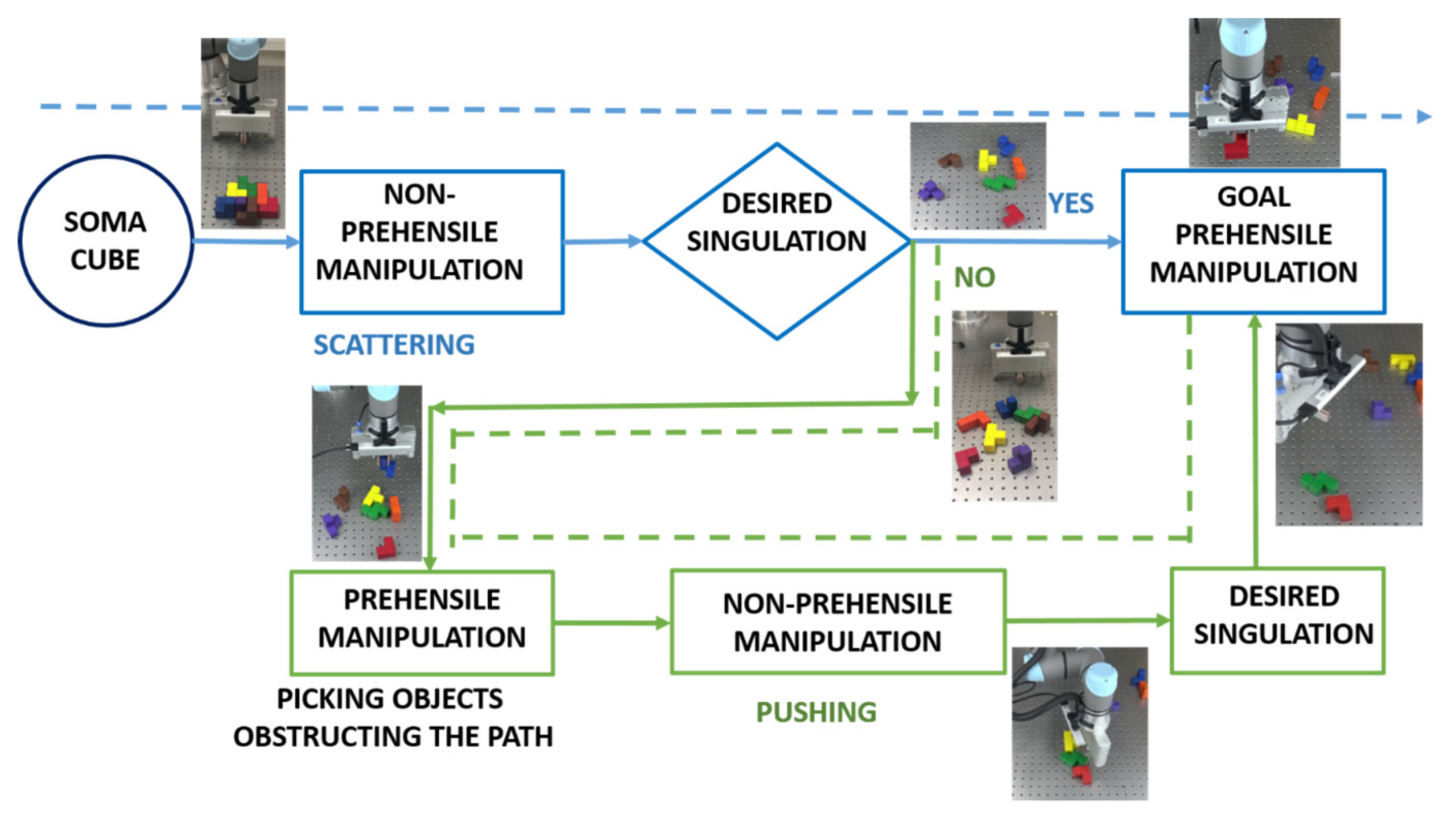
2. Methodology
- (i) Step 1: Dynamic singulation approach by scattering
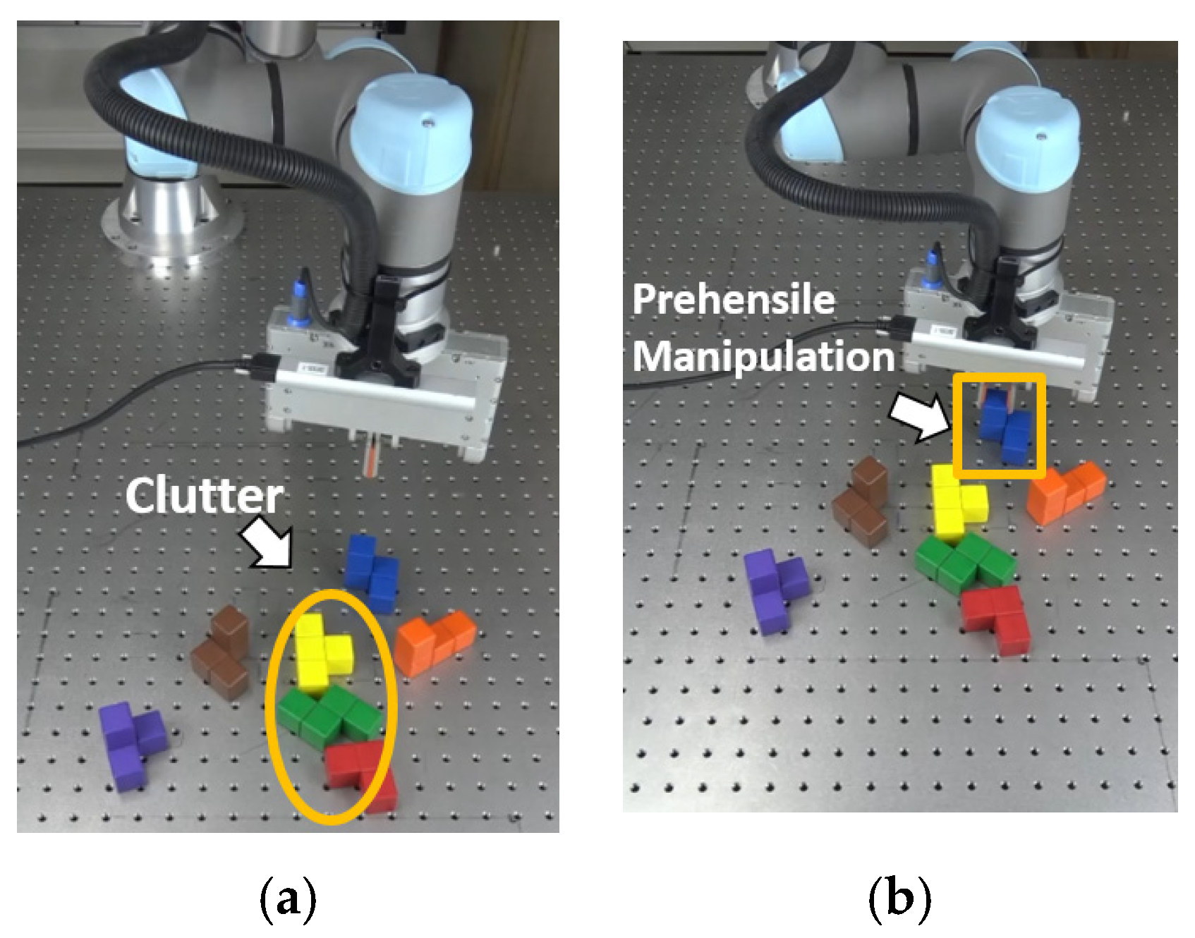
- Purpose: separation of objects in short time to make the size of cluster * smaller
- (* cluster: a group of blocks that are too close to each other for grasping)
- (ii) Step 2: Quasi-static singulation approach by Pushing
- Purpose: separation of objects in small cluster group
3. Modeling, Identification and Condition for Dynamic and Quasi-Static Manipulation
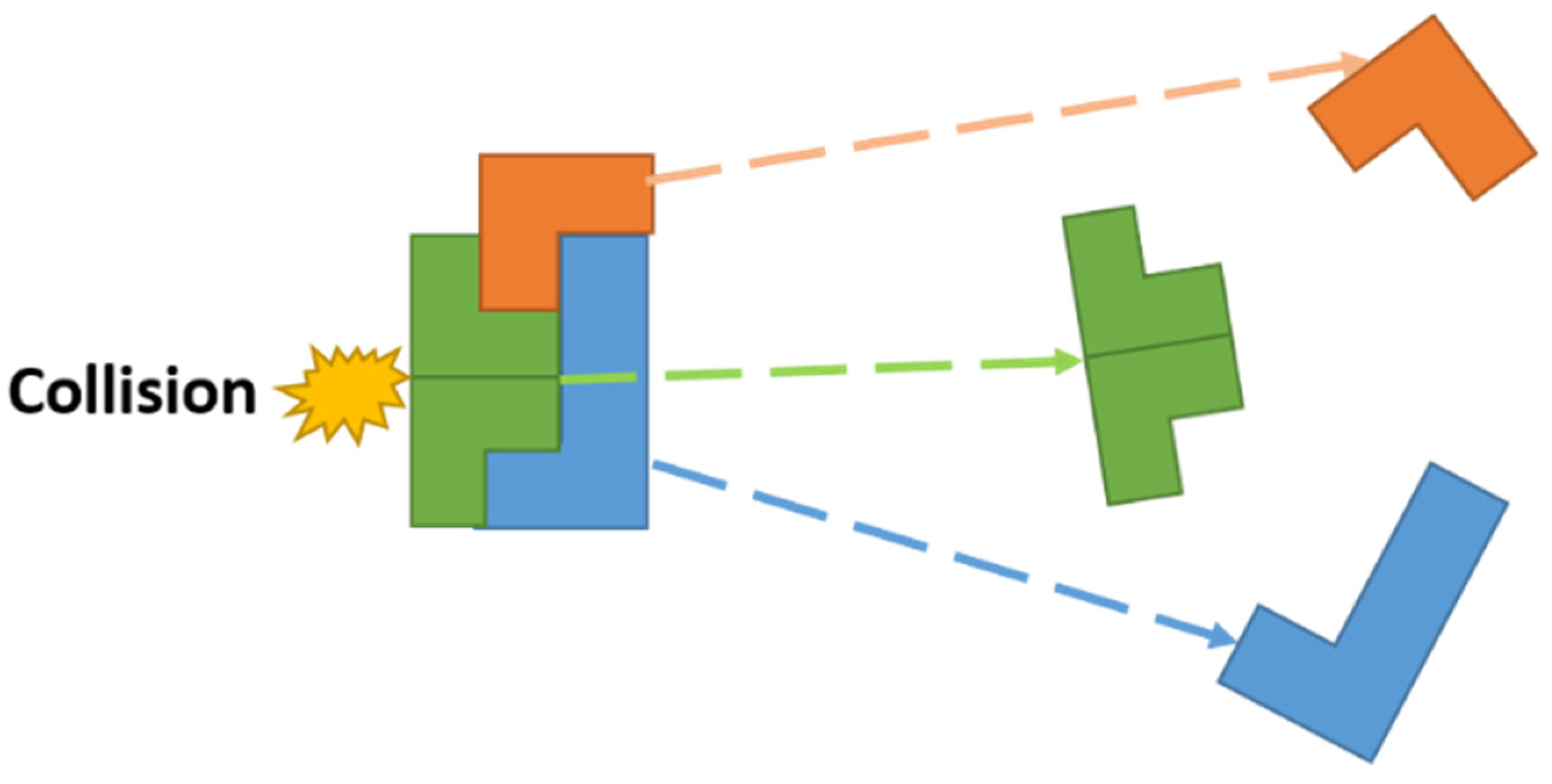
3.1. Impulse Modeling
3.2. Conditions for Quasi-Static and Dynamic Manipulation
4. Parameter Estimation and Simulator Based Dynamic Manipulation
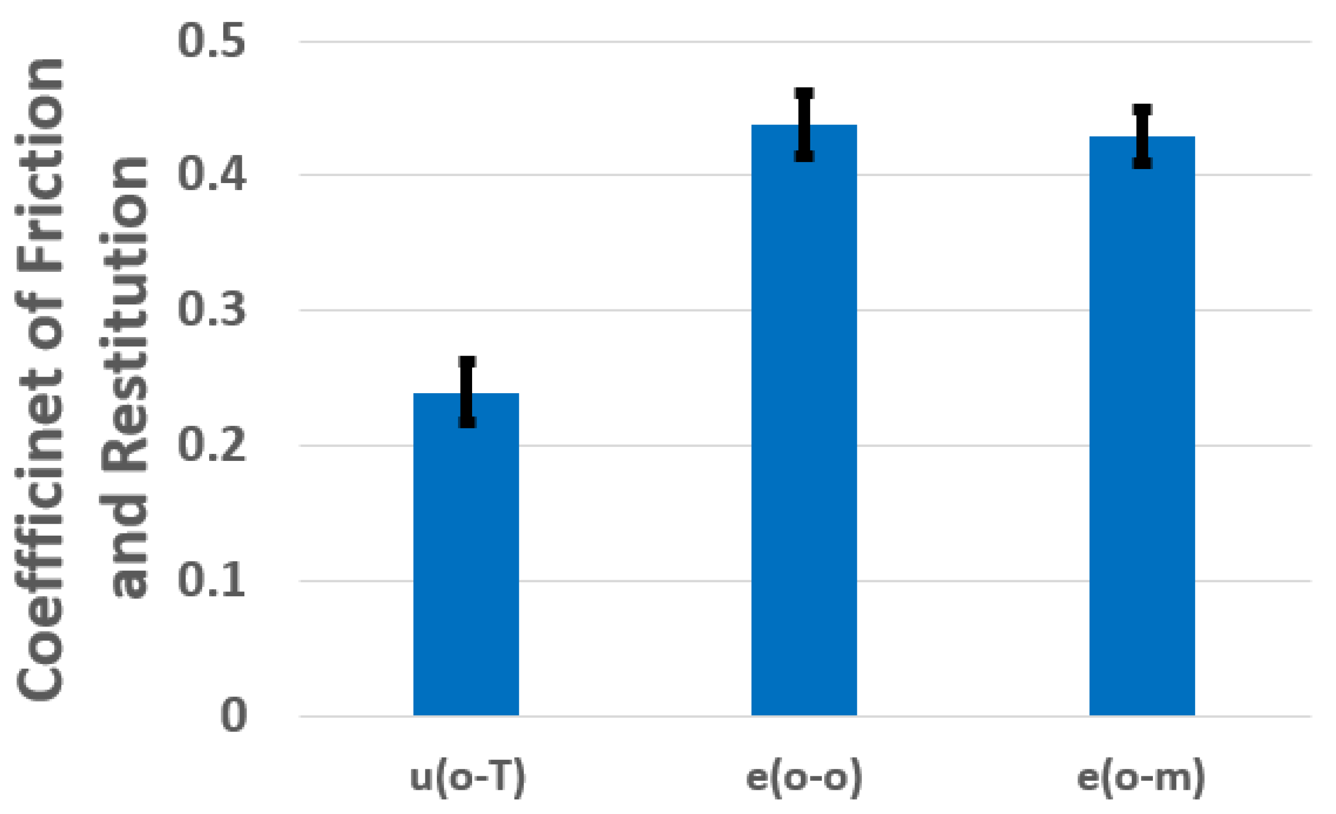
4.1. Estimation of Physicial Parameters
4.2. Coefficient of Restitution
4.3. Simulator-Based Dynamic Manipulation
5. Dynamic, Quasi-Static Manipulation, and Hybrid Approach for Singulation
- (i)
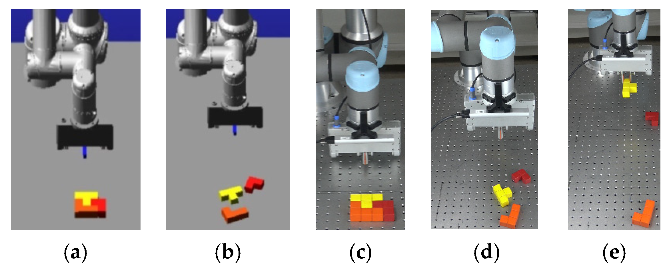
- Case 1: complete singulation of blocks by one time scattering
- (ii)
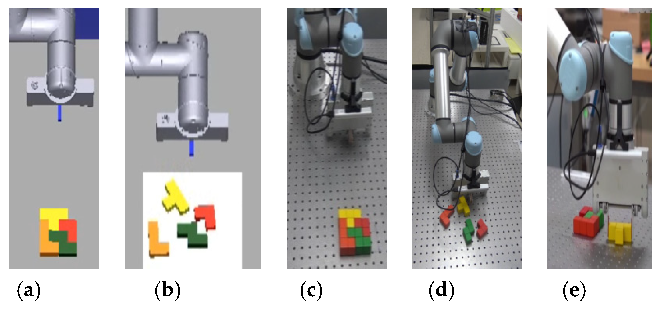
- Case 2: complete singulation of blocks by pure pushing
- (iii)
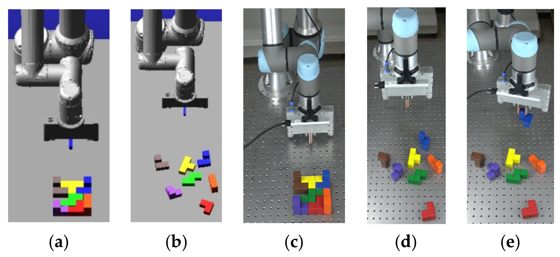
- Case 3: incomplete singulation of blocks by one time scattering, followed by several steps of pushing
5.1. Dynamic Manipulation or Singulation by Scattering
5.2. Quasi-Static Manipulation or Singulation by Pushing
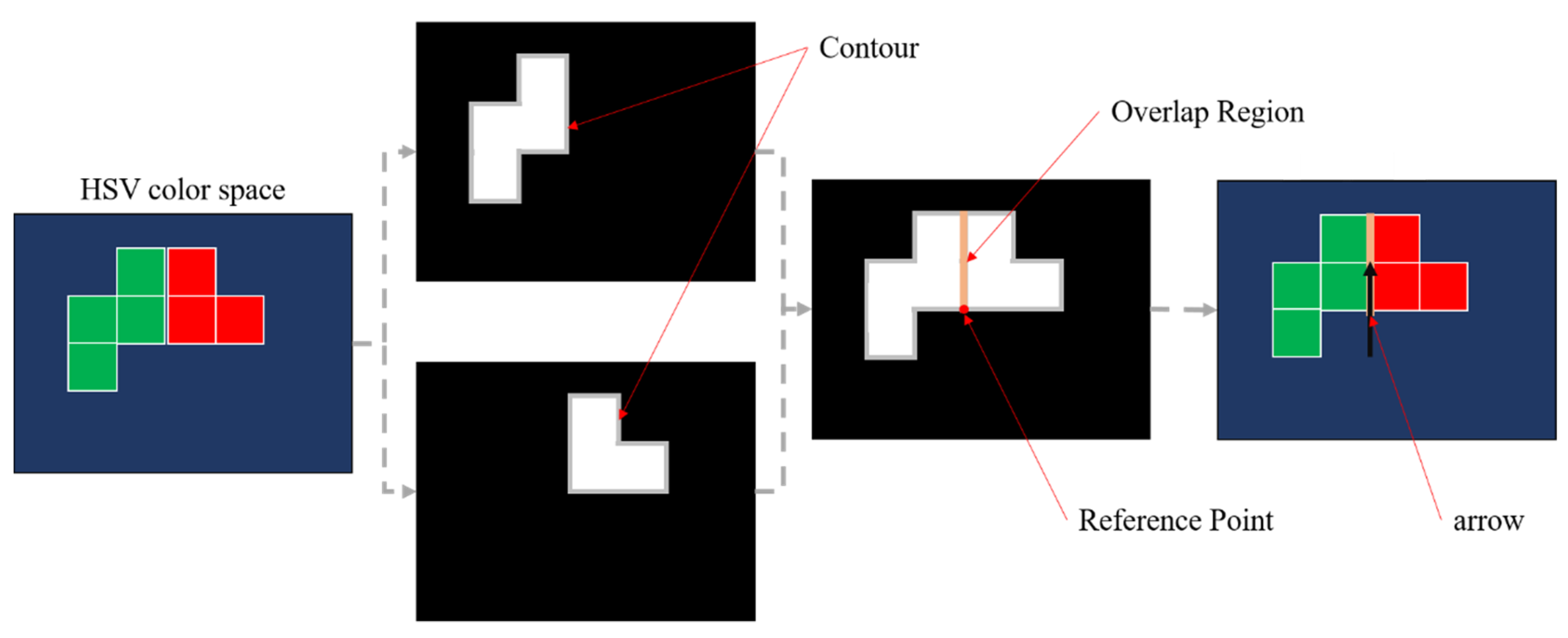
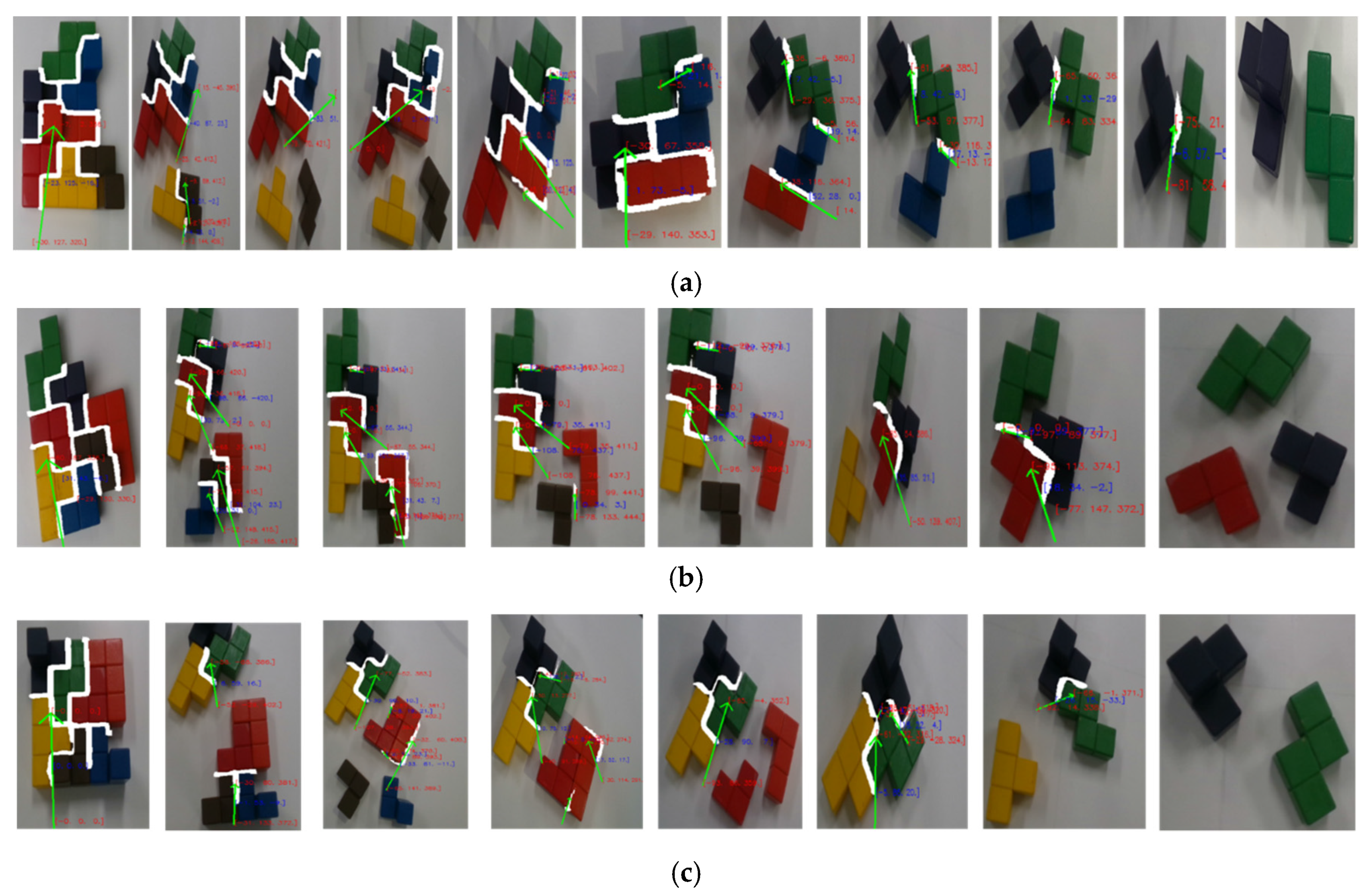
5.2.1. Image Segmentation
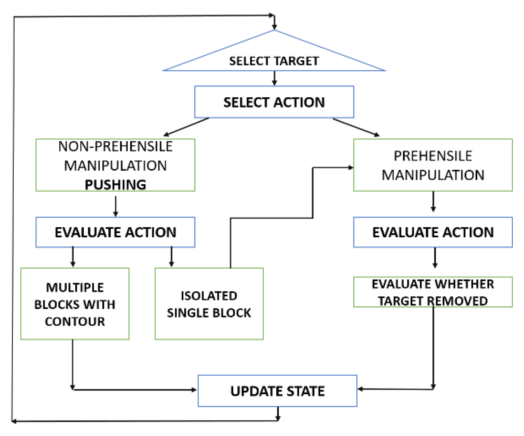
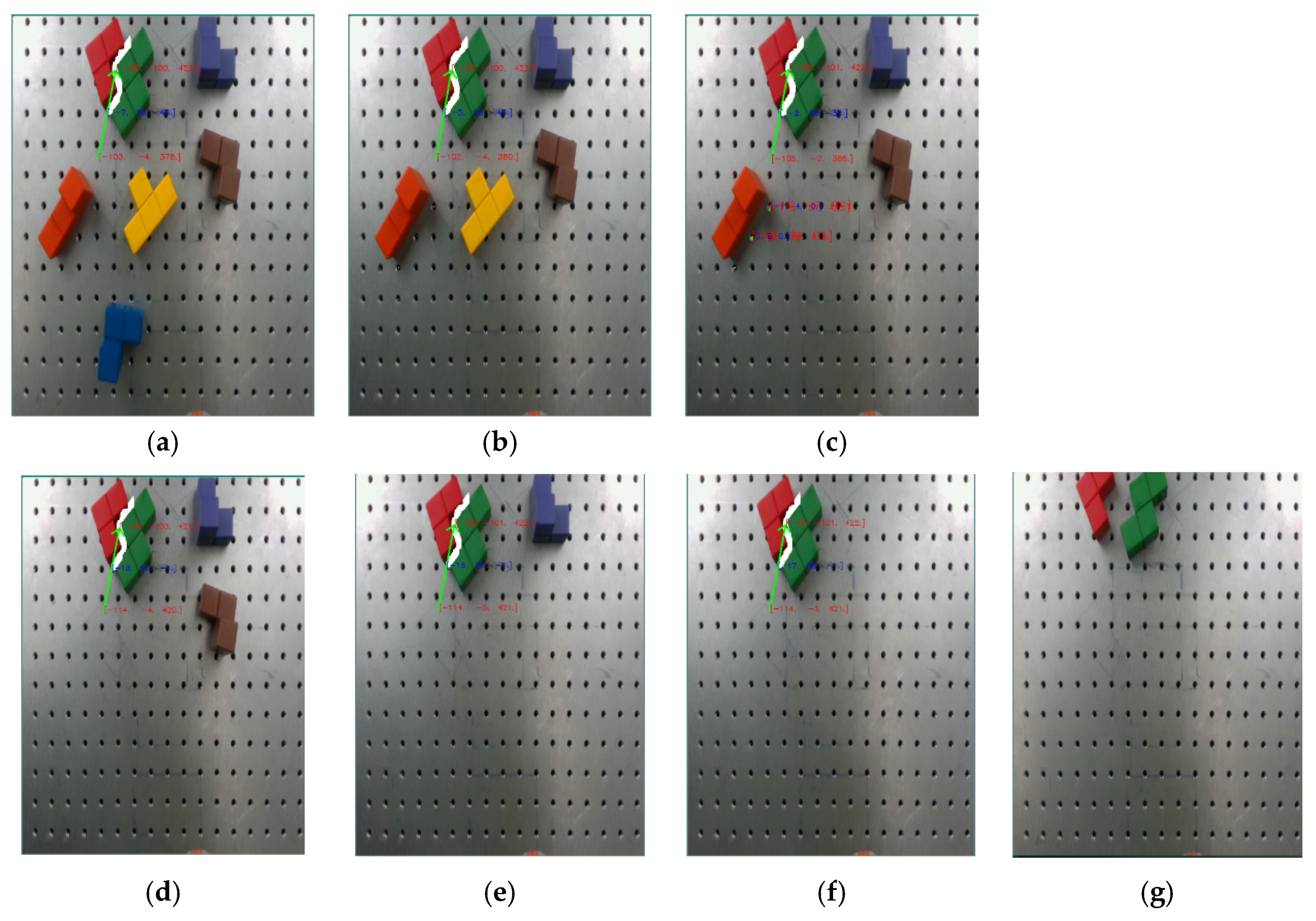
5.2.2. Pushing Algorithm
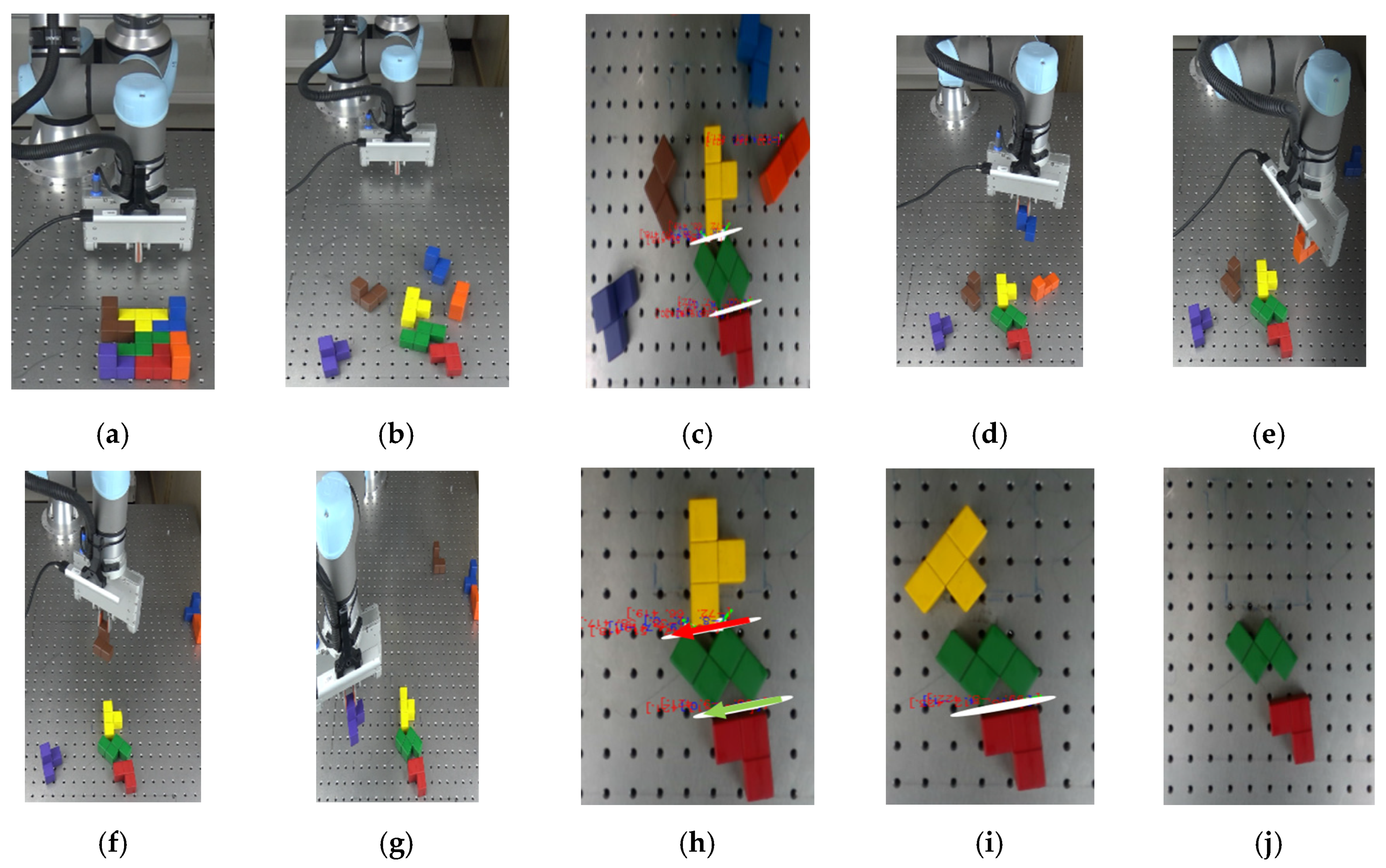
5.3. Hybrid Singulation
6. Comparative Analysis between Hybrid Singulations vs. Pure Pushing and One Time Scattering Singulation
7. Discussion
8. Conclusions
Author Contributions
Funding
Conflicts of Interest
Abbreviations
| Actuated joint | |
| e | Coefficient of Restitution |
| Coefficient of Friction Between Objects | |
| Coefficient of Friction Between Object and Manipulator | |
| Effective Force Vector | |
| Gravity Load | |
| HSV | Hue, Saturation, Value |
| Inertia of Body A | |
| Inertia Matrix | |
| Mass of Body A | |
| Normal Vector | |
| PCA | Principal Component Analysis |
| Inertial Power array | |
| RGB | Red Green Blue |
| T | Transpose of Matrices and Vectors |
| Velocity of Robot | |
| Velocity of Robot | |
| Mass Center Velocity of Body A | |
| Post Impact Velocity of Body A | |
| Angular velocity of Body A | |
| Coefficient of Friction Between Object and Table | |
| Joint Torque |
References
- Dogar, M.; Srinivasa, S. A framework for push-grasping in clutter. In Proceedings of the Robotics: Science and Systems VII, University of Southern California, Los Angeles, CA, USA, 27–30 June 2011; Volume 1. [Google Scholar]
- Kelley, R.B.; Martins, H.A.; Birk, J.R.; Dessimoz, J.-D. Three vision algorithms for acquiring workpieces from bins. Proc. IEEE 1983, 71, 803–820. [Google Scholar]
- Jacobson, L.; Wechsler, H. Invariant image representation: A path toward solving the bin-picking problem. In Proceedings of the IEEE International Conference on Robotics and Automation, Atlanta, GA, USA, 13–15 March 1984; Volume 1, pp. 190–199. [Google Scholar]
- Cosgun, A.; Hermans, T.; Emeli, V.; Stilman, M. Push planning for object placement on cluttered table surfaces. In Proceedings of the IEEE/RSJ International Conference on Intelligent Robots and Systems, Francisco, CA, USA, 25–30 September 2011; pp. 4627–4632. [Google Scholar]
- King, J.E. Robust Rearrangement Planning Using Nonprehensile Interaction. Ph.D. Dissertation, Carnegie Mellon University, Pittsburgh, PA, USA, 2016. [Google Scholar]
- Scholz, J.; Levihn, M.; Isbell, C.; Wingate, D. A physics-based model prior for object-oriented mdps. In Proceedings of the International Conference on Machine Learning, Beijing, China, 21–26 June 2014; pp. 1089–1097. [Google Scholar]
- Marios, K.; Sotiris, M. Robust object grasping in clutter via singulation. In Proceedings of the IEEE International Conference on Robotics and Automation, Montreal, QC, Canada, 20–24 May 2019; pp. 1596–1600. [Google Scholar]
- Hermans, T.; Li, F.; Rehg, J.M.; Bobick, A.F. Learning contact locations for pushing and orienting unknown objects. In Proceedings of the 13th IEEE-RAS International Conference on Humanoid Robots, Atlanta, GA, USA, 15–17 October 2013; pp. 435–442. [Google Scholar]
- Kopicki, M.; Zurek, S.; Stolkin, R.; Mörwald, T.; Wyatt, J. Learning to predict how rigid objects behave under simple manipulation. In Proceeding of the IEEE International Conference on Robotics and Automation, Shanghai, China, 9–13 May 2011; pp. 5722–5729. [Google Scholar]
- Zhu, S.; Kimmel, A.; Bekris, K.E.; Boularias, A. Fast model identification via physics engines for data-efficient policy search. arXiv 2017, arXiv:1710.08893. [Google Scholar]
- Pinto, L.; Gupta, A. Supersizing self-supervision: Learning to grasp from 50 k tries and 700 robot hours. In Proceeding of the IEEE International Conference on Robotics and Automation, Stockholm, Sweden, 16–21 May 2016; pp. 3406–3413. [Google Scholar]
- Levine, S.; Pastor, P.; Krizhevsky, A.; Ibarz, J.; Quillen, D. Learning hand-eye coordination for robotic grasping with deep learning and large-scale data collection. Int. J. Robot. Res. 2018, 37, 421–436. [Google Scholar] [CrossRef]
- Katz, D.; Pyuro, Y.; Brock, O. Learning to manipulate articulated objects in unstructured environments using a grounded relational representation. In Robotics: Science and Systems; MIT Press: Cambridge, MA, USA, 2008. [Google Scholar]
- Katz, D.; Brock, O. Extracting planar kinematic models using interactive perception. In Unifying Perspectives in Computational and Robot Vision; Springer: Berlin/Heidelberg, Germany, 2008; pp. 11–23. [Google Scholar]
- Imran, A.; Kim, S.-H.; Park, Y.-B.; Suh, I.H.; Yi, B.-J. Singulation of Objects in Cluttered Environment Using Dynamic Estimation of Physical Properties. Appl. Sci. 2019, 9, 3536. [Google Scholar] [CrossRef] [Green Version]
- Walker, I.D. Impact configurations and measures for kinematically redundant and multiple armed robot systems. IEEE Trans. Robot. Autom. 1994, 10, 670–683. [Google Scholar] [CrossRef]
- Imran, A.; Yi, B.-J. Impulse modeling and new impulse measure for human-like closed-chain manipulator. IEEE Robot. Autom. Lett. 2016, 1, 868–875. [Google Scholar] [CrossRef]
- Available online: http://www.virtualmotion.co.kr/ (accessed on 8 December 2019).
- Dogar, M.R.; Srinivasa, S.S. A planning framework for non-prehensile manipulation under clutter and uncertainty. Auton. Robot. 2012, 33, 217–236. [Google Scholar] [CrossRef]


| Formations | 7 Block (Pure Pushing) | 7 Block Hybrid Approach |
|---|---|---|
| Number of Experiment | 5 | 5 |
| Success/Fail | 5/0 | 5/0 |
| Average Time (sec) | 30.28 | 6.71 |
| Standard Deviation | 2.69 | 2.13 |
| Coefficient of Variation (CV)% | 8.88 | 31.84 |
Publisher’s Note: MDPI stays neutral with regard to jurisdictional claims in published maps and institutional affiliations. |
© 2020 by the authors. Licensee MDPI, Basel, Switzerland. This article is an open access article distributed under the terms and conditions of the Creative Commons Attribution (CC BY) license (http://creativecommons.org/licenses/by/4.0/).
Share and Cite
Khan, M.U.A.; Imran, A.; Kim, S.; Hwang, H.; Lee, J.Y.; Lee, S.; Yi, B.-J. Scattering or Pushing for Object Singulation in Cluttered Environment: Case Study with Soma Cube. Appl. Sci. 2020, 10, 9153. https://doi.org/10.3390/app10249153
Khan MUA, Imran A, Kim S, Hwang H, Lee JY, Lee S, Yi B-J. Scattering or Pushing for Object Singulation in Cluttered Environment: Case Study with Soma Cube. Applied Sciences. 2020; 10(24):9153. https://doi.org/10.3390/app10249153
Chicago/Turabian StyleKhan, Muhammad Umair Ahmad, Abid Imran, Sanghwa Kim, Hyunho Hwang, Ji Yeong Lee, Sungon Lee, and Byung-Ju Yi. 2020. "Scattering or Pushing for Object Singulation in Cluttered Environment: Case Study with Soma Cube" Applied Sciences 10, no. 24: 9153. https://doi.org/10.3390/app10249153