
In Vivo Usability Test of Vascular Intervention Robotic System Controlled by Two Types of Master Devices


1
Department of Electrical and Electronic Engineering, Hanyang University, Ansan 15588, Gyeonggi-do, Korea
2
Department of Research Institute of Engineering & Technology, Hanyang University, Ansan 15588, Gyeonggi-do, Korea
3
Department of Radiology, Research Institute of Radiological Science, Yonsei University College of Medicine, Seoul 03722, Korea
*
Authors to whom correspondence should be addressed.
Appl. Sci. 2021, 11(12), 5453; https://doi.org/10.3390/app11125453
Submission received: 22 May 2021
/
Revised: 8 June 2021
/
Accepted: 10 June 2021
/
Published: 11 June 2021
(This article belongs to the Special Issue Frontiers in Medical Robotics)
Abstract
:Conventional vascular intervention (VI) procedures are typically performed manually under exposure to X-rays, whereby several problems are presented that need to be addressed owing to the patients and doctors being exposed to large amounts of radiation. In such cases, employing radiation protection units is not a long-term solution to avoid physical damage. Therefore, to overcome these issues, we propose a robotic VI system in this study. Moreover, we compare the extent of radiation exposure in the case of the conventional manual VI procedure with that in the case of the robotic procedure. The radiation exposure is then analyzed from the perspective of the doctor. Subsequently, the results of usability tests for two proposed master devices are presented in terms of the NASA task load index (NASA-TLX) and the system usability scale (SUS) score. To verify the effectiveness of the robotic VI system, animal experiments are conducted using a pig model. Among the two types of master devices tested with the proposed robotic VI system, the ergonomically designed 2-degree-of-freedom master device is found to be more effective than the joystick-type device in terms of the usability test scores. Hence, the proposed robotic VI procedure is shown to be advantageous in terms of reducing radiation exposure and improving usability.
1. Introduction
Conventional vascular intervention (VI) procedures are used to diagnose and treat diseases of the vascular system with the aid of catheters, guidewires, and various interventional devices, such as balloons and stents, with minimal incisions. These procedures require the use of imaging guidance methods, such as fluoroscopy, computed tomography (CT), magnetic resonance imaging (MRI), and other imaging modalities. Angiography, embolization, and angioplasty are the most frequently performed vascular interventional procedures worldwide [1,2,3,4,5,6]. During conventional VI procedures, both patients and doctors are exposed to large amounts of radiation from CT or X-rays. Such exposure has a detrimental effect on human health. For example, radiation exposure can cause skin damage, which can potentially lead to carcinogenesis as the radiation damage from repeated VI procedures accumulates [7].
Radiation dose limits for individuals subjected to occupational exposure are regulated by the international commission on radiation protection (ICRP). According to the ICRP 103 recommendations [8], the effective dose limit for radiation workers is 50 mSv per year; moreover, an additional recommendation is an effective dose limit of less than 20 mSv per year on average over five years. To prevent occupational radiation exposure, radiation workers wear radiation protectors in the form of aprons, collars, glasses, and gloves. However, they may become physically fatigued owing to the weight of the apron. Moreover, as radiation protection gloves are used minimally during surgical procedures in the operating room, exposure doses on the hands are still high [2]. To overcome these shortcomings, remote operations using master/slave robotic systems are needed for VI procedures to minimize radiation exposure.
Many research groups have developed VI robotic systems, such as the remote-controlled robotic system [9], VI surgical robot [10], CorPath GRX robotic system [11], Magellan robotic system [12], stereotaxis system, sensei robotic system [13], and COAST guidewire robot [14]. The effectiveness and feasibility of these developed VI robotic systems have been verified through numerous clinical trials for various VI procedures.
The main goal of developing the VI robotic system is to reduce the radiation exposure that occurs in the VI procedure, control the precise movement of the surgical tool, and reduce the physical fatigue of the doctor. Zhou et al. [9] and Yu et al. [10] demonstrate in vitro experiments, both systems have elaborated manipulating surgical tool using force feedback.
In the clinical trials of the CorPath GRX robotic system, percutaneous coronary intervention with manipulation of coronary guidewires was conducted on eight patients. The performance of the robotic system was evaluated and reported to be equal to or better than that in the case of the manual procedure [15].
Since the release of the first clinical report of the Hansen Sensei Robotic system in endovascular abdominal aortic aneurysm repair [16], the Magellan robotic system with six French catheter systems has been used to conduct more complicated procedures such as fenestrated endovascular aneurysm repair [17] or thoracic endovascular aortic repair.
Clinical trials for thoracic aortic repair using the Magellan robotic system have shown significantly less cerebral embolization when compared to that in the case of manual techniques in 11 patients [18]. The study concluded that due to its active maneuverability, control, and stability, the robotic system is likely to reduce contact with the atheromatous aortic arch wall, thereby resulting in less cerebral embolization.
However, these robots face limitations when operating with only catheters and guidewires. Robots with catheter and guidewire drives are suitable for cardiovascular interventions targeting large vessels. However, it is difficult to use these robots for procedures targeting microvascular lines. For example, the treatment of the transarterial embolization of liver tumor requires the operation of microcatheters and micro guide wires.
The microbot medical Inc. have developed the LIBERTY system to overcome these challenges. LIBERTY is a fully disposable robot system that can drive micro guide wire and microcatheter. The LIBERTY system showed the possibility of microvascular treatment of the robotic system by conducting coil deploy experiment on micro vessels through animal experiments [19]. The LIBERTY system also has the merit of reducing radiation exposure of doctors because it can be operated remotely.
To overcome the limitations of the developed VI robotic systems, we modified a 4- and 5-degree of freedom (DOF) VI robotic system previously developed by us [20,21]. The modified VI robotic system has 7 DOFs to drive the co-axial catheter–microcatheter system including catheters (5–7 French), guidewires (0.035 inch), microcatheters (3 French), and micro guide wires (0.012–0.018 inch).
In this study, we compared the radiation exposure dose that the doctor received during the robotic and conventional VI procedures. In addition, based on the system usability scale (SUS) score and the NASA task load index (NASA-TLX), a VI robotic system usability test was conducted to compare a 2 DOFs ergonomically designed master device and a joystick-type master device. Subsequently, in vivo experiments were conducted using a pig model to measure the radiation exposure dose received by the doctor and analyze the results of the usability tests of the two types of master devices.
2. 7 DOFs VI Robotic System
2.1. 7 DOFs VI Slave Robot
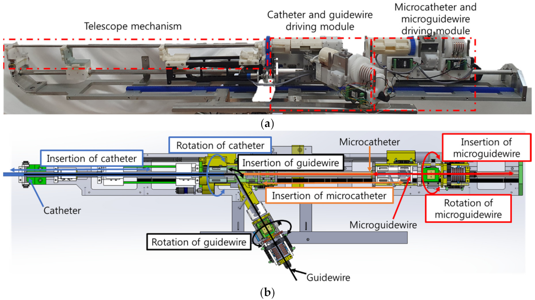
In this study, a 7 DOFs VI slave robot system was developed to control the motions of the catheter, guidewire, microcatheter, and micro guide wire. Figure 1a shows the 7 DOFs VI slave robot proposed in this study, which is a modified version of that developed by Cha et al. [20,21,22]. Cha et al. developed a 4 and 5 DOFs robotic systems for vascular intervention. The 4 DOFs robotic system controls the guidewire and the catheter, and the 5 DOFs robotic system includes steerable catheter. The unique feature of the 7 DOFs VI slave robot is that it employs a two-way design to minimize the total length of the robotic system. The front part of 7 DOFs VI slave robot is used to drive the guidewire and the catheter, and the longitudinal part is used to control the motion of the micro guidewire and the microcatheter.
The 7 DOFs VI slave robot employs a telescopic mechanism in the central axis to control the catheter, as shown in Figure 1b. The guidewire moves sideways through the y-connector; this is done to enable the installation of up to four intervention tools on the 7 DOFs VI slave robot at once before conduction of the procedure so that the operator does not need to intervene during the VI procedure. The 7 DOFs VI slave robot can implement catheter rotation/insertion, guidewire rotation/insertion, microcatheter insertion, and micro guide wire rotation/insertion motions, as shown in Figure 1b.
To use the VI robotic system in a real operating room, it is necessary to consider the installation of the VI robotic system. During the VI procedure, the position of the bed and the C-arm are required to be freely adjustable. Therefore, the proposed VI slave robot was developed in the form of a bed mounting to maintain the robot’s position with respect to the patient. In addition, a 5 DOFs robot arm is used to adjust the position of the VI slave robot such that it could approach the patient’s treatment area in the right direction. The movement of the 5 DOFs robotic arm is shown in Figure 2a. For user convenience, a motor and a brake were installed at each joint of the 5 DOFs arm. In the case of normal operation, when power is supplied to the 5 DOF robot arm, the brake on the robot arm is released so that the robot arm can be properly positioned. Conversely, in the event of an emergency when the power supply is not stable, the brake on the 5 DOF robot arm is locked to ensure patient safety. The position of the VI robot was adjusted by operating the handle. The force/torque sensor (ROBOTUS, RFT40) installed on the handle of the 5 DOFs robot arm is employed to position the handle easily using an admittance control algorithm.
The 7 DOFs VI slave robot thus mounted on the side of the bed with the 5 DOFs robot arm is shown in Figure 2b.
When the user operates the handle, the measured force and torque are converted to a position command of the 5 DOFs robot arm through admittance control according to the expression
where is the admittance gain matrix.
2.2. Master Devices of AI Robotic System
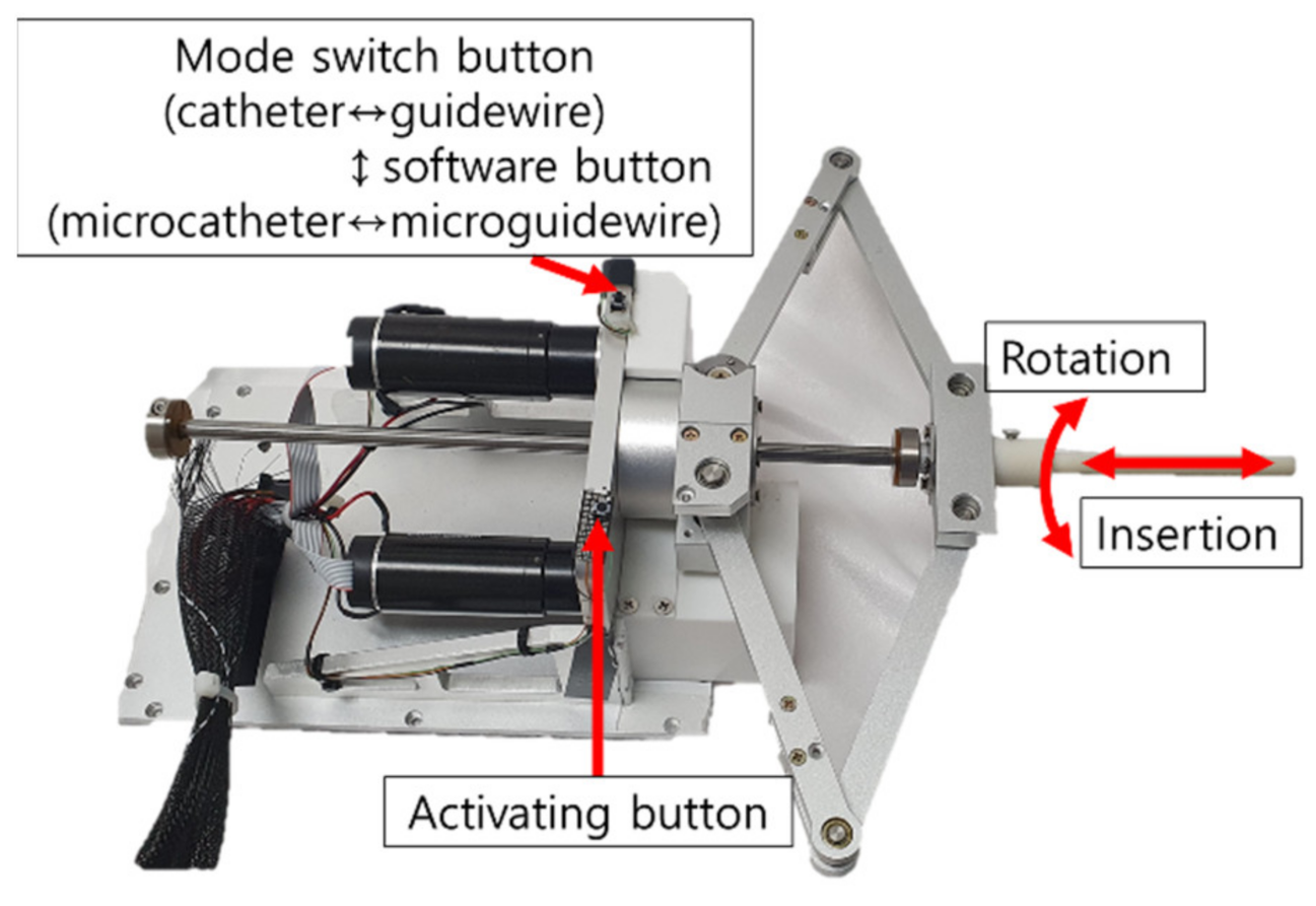
In this study, two types of master devices were tested in the in vivo experiments. The first master device has 2 DOFs, as shown in Figure 3. The motion of this device was inspired by the movement of the operator’s hand during the VI procedure. In the conventional VI procedure, the catheter and guidewire are manually operated. Thus, the ergonomically designed 2 DOFs master device was implemented to involve the same motions as those in the conventional VI procedure.
Upon the activating button being pressed, the command from the master device is transferred to the VI slave robot. Further, a mode switch button is used to change the catheter control mode to the guidewire control mode and vice versa. This master device adopts the position–position control method, where the displacement of the VI slave robot is proportional to that of the master device.
The advantage of the ergonomically designed 2 DOFs master device is that it mimics the movement of the operator’s hand. Therefore, any operator can easily and intuitively use it. Conversely, the disadvantage of this device is that the operator has to perform repetitive motions to send the catheter and the guidewire to the target vessel. Using a motion scale, the operator can easily manipulate the catheter or the guidewire. However, the operator may feel physical burden/fatigue when operating this master device for a long duration.
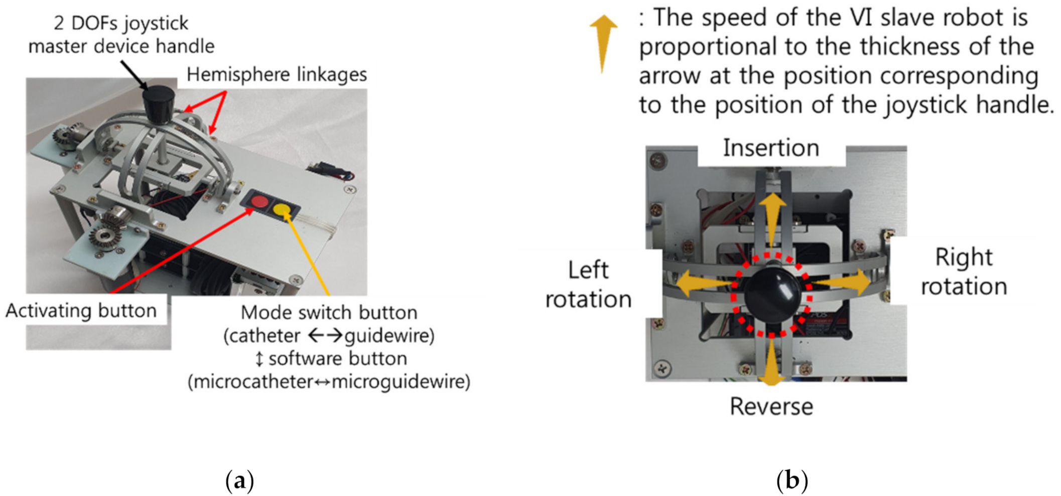
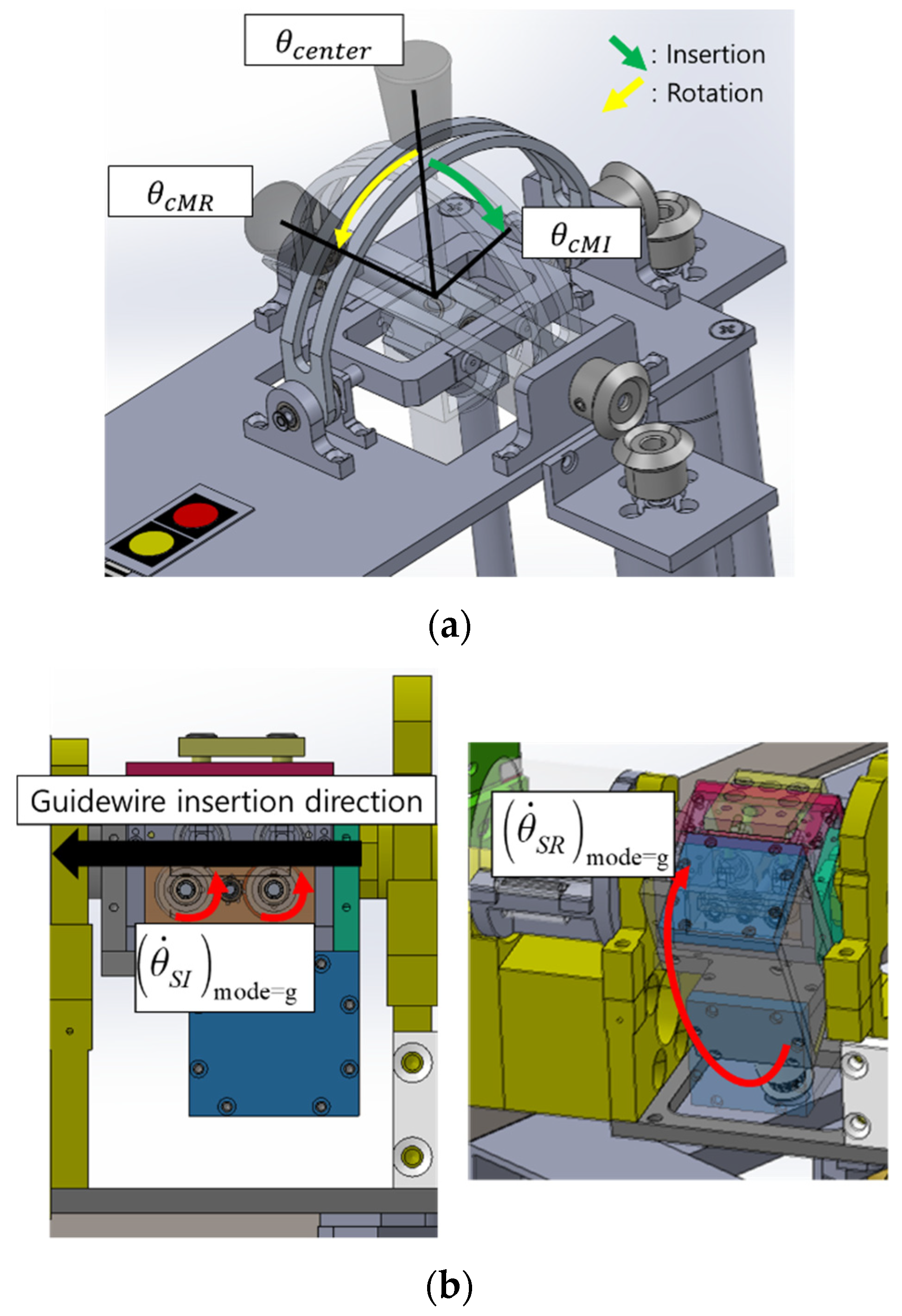
The second master device also has 2 DOFs, as shown in Figure 4a and a joystick-type structure comprising two hemisphere-type linkages. These linkages were coupled to the joystick handle at the center of the device so that insertion and rotation of either the catheter or the guidewire could be achieved using the two rotational degrees of the joystick. Two buttons were placed on the right side of the device. Similar to the ergonomically designed master device, the slave robot could move only when the button was pressed. Further, a mode switch button was used to change the catheter control mode to guidewire control mode and vice versa. The joystick-type master device adopts the position-velocity control strategy, where the velocity of the VI slave robot is proportional to the position command of the master device. In the 2 DOFs joystick-type device, the motion speed of the VI slave robot increased as it moved farther away from the center of the joystick structure.
The merit of the 2 DOFs joystick-type master device with position-velocity control is that the operator does not have to perform repetitive motions, which can save time and physical effort of the operator. The operation of the master device is similar to that of gaming joystick-type device. The disadvantage of the 2 DOFs joystick device, however, is that the operator requires more time to get used to the 2 DOFs joystick master device because the control modes of the conventional VI procedure and 2 DOFs joystick-type device are different.
2.3. 7 DOFs VI Slave Robot Control for the Two Master Devices
As explained in Section 2.1 and Section 2.2, the master–slave VI robotic system is composed of a 2 DOFs master device and 7 DOFs slave robot. To control the slave system, which has more DOFs than the master device does, the mode switching method was applied to select one of the four VI tools (catheter, guidewire, microcatheter, and micro guide wire). The mode switch consists of two buttons: a mode switch button on the master device and a virtual button on the programming software for the 7 DOFs VI slave robot. The mode switch button on the master device was used to change the mode between the catheter and guidewire modules. The same button also changed the mode between the microcatheter and micro guide wire modules. The software button for the 7 DOFs VI slave robot control software was used to change between the catheter–guidewire and microcatheter–guidewire modes. The four modes of the 7 DOFs VI slave robot using the two mode switching buttons are described in Figure 5.
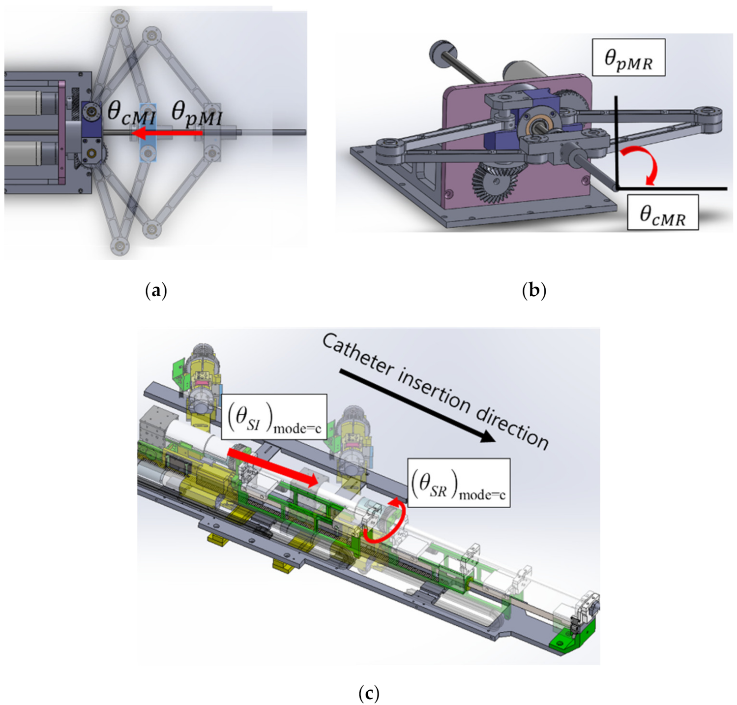
In this work, two different 2 DOFs master devices were used to control the 7 DOFs VI slave robot. The ergonomically designed 2 DOFs master device adopted the position–position control method, as illustrated in Figure 6. When the operation shown in Figure 6a occurred in the ergonomically designed 2 DOFs master device, the insertion motions were transmitted to the 7 DOFs VI slave robot. In addition, when the motion shown in Figure 6b occurred, the rotation motion was transmitted to the slave robot. The movements of the slave robot according to the inputs of the ergonomically designed master device are shown in Figure 6c.
The expressions representing the movements of the 7 DOFs VI slave robot according to the motions of the ergonomically designed 2 DOFs master device are as follows:
where and denote the current and previous positions of the master device handle for insert operation. and denote the current and previous positions of the master device handle for rotate operation. and are the insertion and rotation motions of the VI slave robot position, respectively. Each module has a different control gain and .
The 2 DOFs joystick-type master device adopts the position-velocity control method, as shown in Figure 7. When the operation shown in Figure 7a occurred, the insertion and rotation motions were transmitted to the slave robot. The movements of the slave robot according to the inputs of the joystick-type master device are shown in Figure 7b.
The expressions representing the movements of the slave robot according to the motions of the joystick-type master device are as follows:
where and denote the current and center positions of the joystick-type master device handle for insert operation. and denote the current and previous positions of the master device handle for rotate operation and represent the insertion and rotation of the slave robot velocity, respectively. Each module has a different control gain and , similar to that of the ergonomically designed 2 DOFs master device.
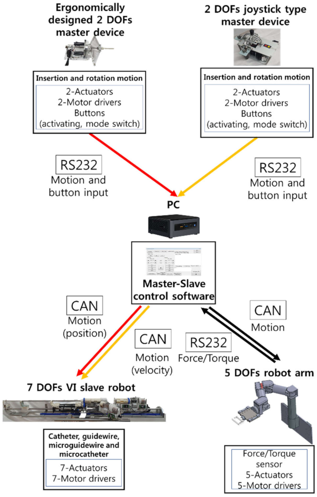
The schematic of the robot control system is presented in Figure 8. The motion data from the master devices were transmitted to a PC via RS232 communication. The motion command was transmitted to the motor controller of the 5 DOFs robot arm and 7 DOFs VI slave robot via controller area network (CAN) communication.
3. In Vivo Experiment
3.1. Experimental Conditions for Measurement of Radiation Exposure
Herein, in vivo experiments were conducted to evaluate the performance of the 7 DOFs VI robotic system. To verify the effectiveness of the system, animal experiments were conducted using a pig model. The Animal Care Committee of the Department of Laboratory Animal Resources of Yonsei University College of Medicine approved this study protocol (Permit number: 2018–0224). In the experiments, the radiation exposure doses were measured for both the conventional and robot-based VI procedures.
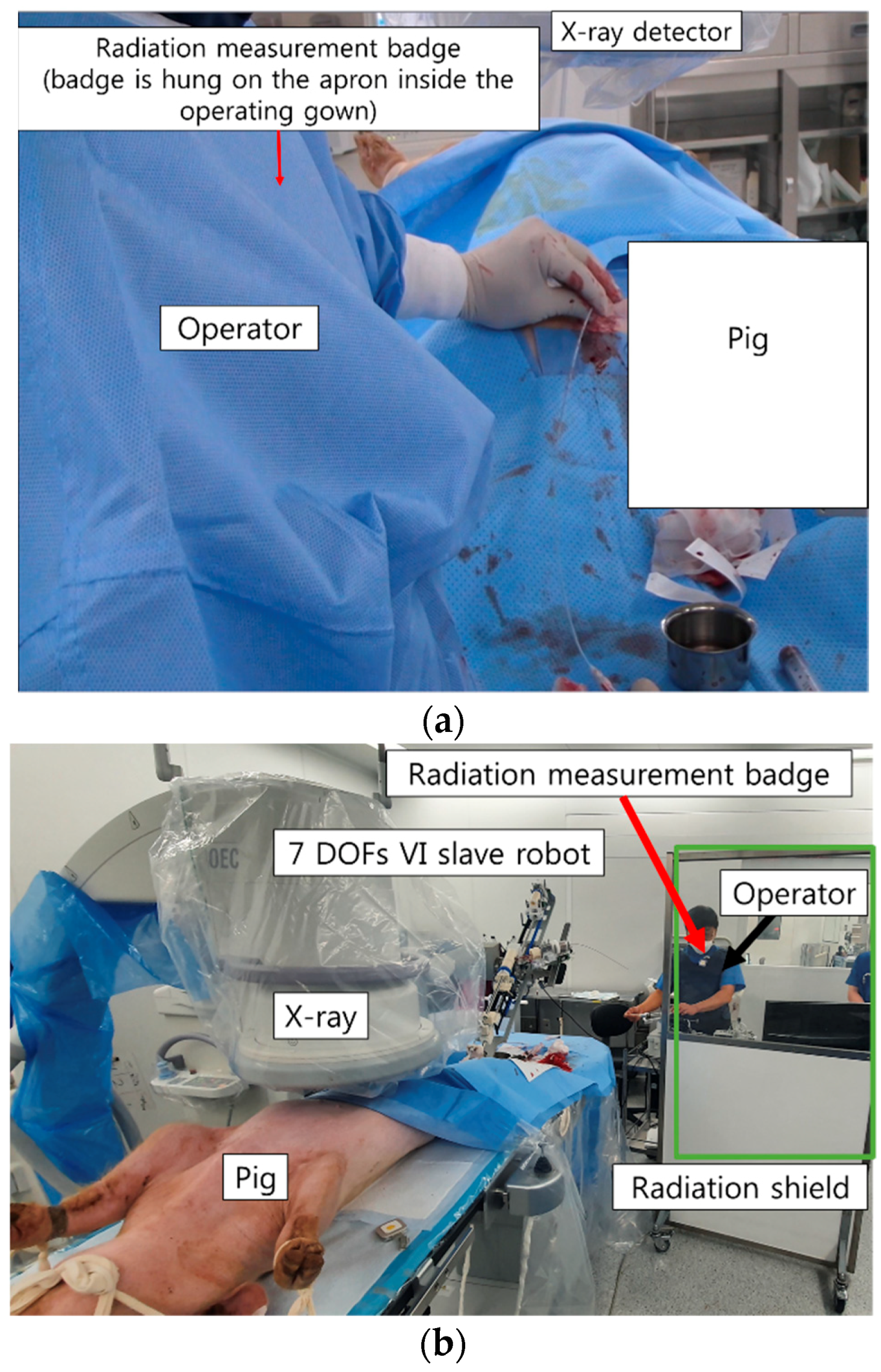
In the conventional procedure, the doctor manipulates the catheter (Sungwon medical, Seoul, Korea) and guidewire (Terumo, Tokyo, Japan) manually; therefore, the doctor has to be located close to the X-ray source, as shown in Figure 9a. In the experiments described in this paper, the console of the master device of the robotic VI system was located inside the procedure room, taking into account emergency situations in the case of human procedures. The distance between the radiation source and the master device was about 5 m, and a lead window shield was placed between them. In this case, the doctor only needs to manipulate the master device to control the catheter and guidewire, and therefore does not have to be present close to the X-ray source, as shown in Figure 9b. The radiation dose was measured using a real-time radiation dosimeter (RaySafe i2, RaySafe, Sweden) at the anterior chest position of the doctor’s apron during the conventional and robotic VI procedures. Real-time radiation dosimetry allows for the measurement of the radiation dose at a certain point in time as well as the accumulated radiation dose for each procedure. A total of 10 doctors participated in the radiation exposure measurement tests for procedures involving a selection of the pig’s hepatic, splenic, and right renal arteries. Ten doctors participated in the VI robot system usability test. Among them, six doctors had never used the VI robot system used in this study before, three doctors had 2 or 3 prior experiences with the VI robot, and one doctor had operated VI robot more than 30 times. In addition, the expert level of the doctors participating in the experiment is diversely distributed from 1 year to over 20 years in the department of radiology.
3.2. Usability Tests of Two Different Master Devices for Robotic VI System
In this study, we analyze the usability of the two master devices. The same targets were employed for the measurement of the radiation exposure. Two different target points were each selected for the hepatic and right renal arteries to analyze the usability of the two master devices. The completion times were measured when the catheter and guidewire reached the target points of the in vivo vessels. The NASA-TLX [23] was used as an additional index for comparing the two devices. The NASA-TLX questionnaire was used to measure the workload. Further, the SUS score [24] was measured.
The NASA-TLX is a widely used, multidimensional assessment tool that rates perceived workload to assess a task, system, or team’s effectiveness or other aspects of performance. It was developed by the Human Performance Group at NASA’s Ames Research Center. The NASA-TLX has six evaluation criteria: mental demand, physical demand, temporal demand, performance level, effort level, and frustration level. The NASA-TLX criteria are evaluated for each task within a range of 100 points in 5-point steps. For example, if a task does not require significant mental effort to complete, a low score is assigned to the mental demands question, and vice versa. In conclusion, the lower the test subject’s NASA-TLX score, the lower the mental and physical demands required to complete the task.
The SUS score was originally created by John Brooke in 1986. It was used to evaluate a wide variety of products and services, including hardware, software, and applications. Each item of the SUS score has five response options for respondents, ranging from strongly agree to strongly disagree. The SUS score involves 10 items that evaluate the level of consent and aims to assess the system by combining the positive and negative aspects of its performance. The SUS score generally provides a high level of subjective perspective on the usefulness of the system. As a method of analyzing the SUS score, Bangor et al. [25] developed the evaluation criteria for the SUS scores. Bangor et al. assigned terms of what is “acceptable” or “not acceptable” for the SUS score. The acceptable range corresponds to scores of above 70 and the unacceptable range corresponds to scores below 50. Additionally, Bangor et al. designated the range between 50 and 70 as “marginally acceptable”. For the VI robotic system usability test, we asked the subjects to fill out the NASA-TLX and SUS score questions after completing the task for each device.
4. In Vivo Experiment Results
4.1. Pig Hepatic and Splenic Arteries
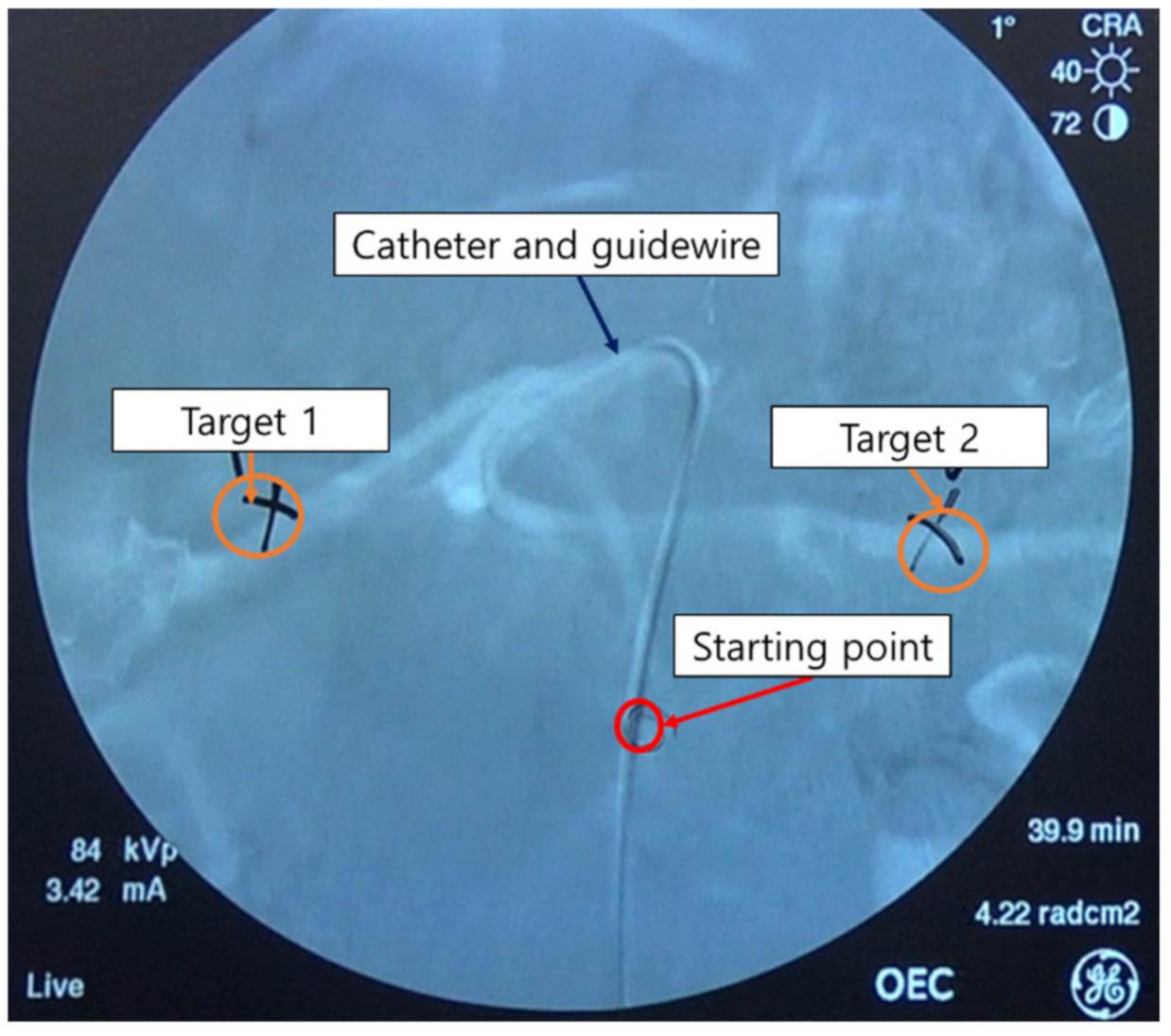
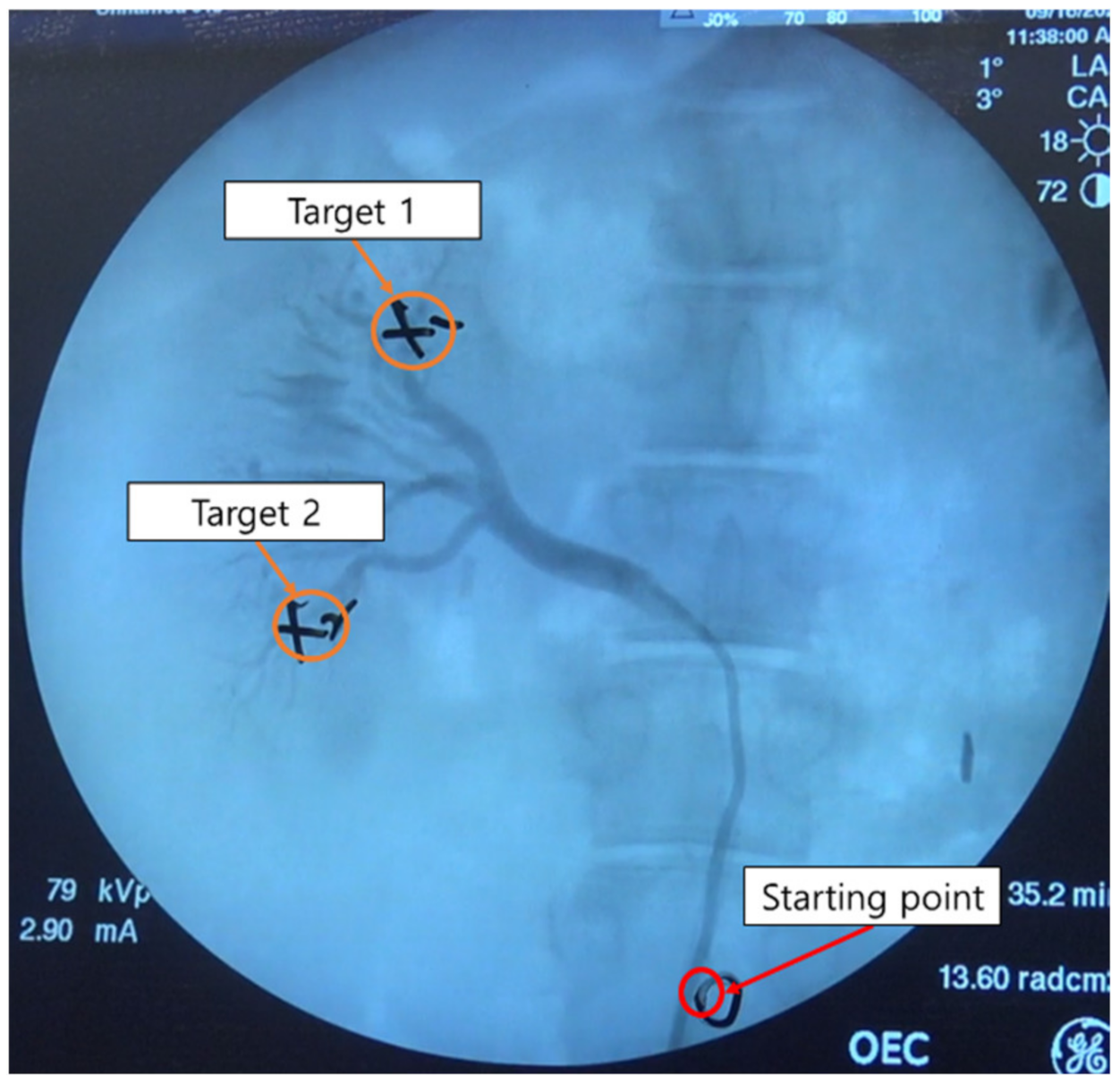
To measure the operator radiation exposure and the usability of the two master devices for the robotic systems, the starting and target points (target 1 = hepatic artery, target 2 = splenic artery) were set as shown in Figure 10. The experiments for the hepatic and splenic arteries were conducted three times per target per master device per operator.
Figure 11 shows the results of the radiation exposure measurements of the operator during the conventional and robotic procedures. For the conventional procedure for target 1, the radiation exposure was measured to be 4.38 ± 1.95 µSv, whereas that for the robotic procedure for target 1 was measured to be 0.11 ± 0.04 µSv. For target 2, the radiation exposure doses were measured to be 6.16 ± 1.86 µSv and 0.12 ± 0.06 µSv for the conventional and robotic VI procedures, respectively. In the hepatic and splenic artery experiments, it was observed that the robotic procedure reduced radiation exposure by about 97% compared to the conventional procedure.
For the pig hepatic and splenic artery experiments, the NASA-TLX and SUS scores were used to evaluate the usability. The results of the overall workload score based on the NASA-TLX and the system integration score evaluation based on the SUS score are summarized in Table 1. The values indicate the mean and standard deviation of the usability scores for the two master devices for each target.
The operators reported higher NASA-TLX scores for both target 1 and target 2 when using the 2 DOFs joystick-type master device, implying that this device is physically and mentally harder to operate. In addition, higher SUS scores were reported for both target 1 and target 2 when using the 2 DOFs ergonomically designed master device. In the case of the 2 DOFs joystick-type master device, the score was about 55 points for both target 1 and target 2. According to the SUS score evaluation criterion, the 2 DOFs joystick-type master device belongs to the “marginal low” category among the acceptability ranges. However, the ergonomically designed 2 DOFs master device received approximately 73 points for the SUS score for the hepatic artery target 1 and target 2. This score is considered “acceptable”. Thus, the 2 DOFs ergonomically designed master device outperformed the 2 DOFs joystick-type device in terms of user work intensity and system integration.
In addition, Table 2 shows the average of moving distances of the two master devices and the number of retractions of surgical instruments during the process of selecting blood vessels to reach the targets. The lesser the moving distance and the number of retractions, the lesser energy the master device consumes.
For both target 1 and target 2, the moving distance of the joystick-type master device was measured to be greater than that of the 2 DOFs ergonomically designed master device. Moreover, the number of retractions of surgical instruments for the 2 DOFs joystick-type master device was measured to be higher than that for the 2 DOFs ergonomically designed master device. In terms of these two quantitative measurements, the 2 DOFs ergonomically designed master device outperformed the 2 DOFs joystick-type device for both the hepatic artery and splenic artery.
4.2. Pig Right Renal Artery
In the case of the right renal artery selection experiment, the starting and target points were set as shown in Figure 12. The selection of the right renal artery was also performed three times for each target and for each master device per operator. Compared to the hepatic and splenic artery experiments, it was easier to approach the target points in the right renal artery experiment.
The results of the measurement of the radiation exposure to operators during the conventional and robotic VI procedures for the right renal artery are shown in Figure 13. In the conventional procedure for the right renal artery target 1, the radiation exposure was measured as 2.84 ± 0.91 µSv, whereas that for the robotic procedure was 0.08 ± 0.04 µSv. Further, for the right renal artery target 2, the radiation exposure doses of the operator were measured as 2.61 ± 0.87 µSv and 0.06 ± 0.02 µSv for the conventional and robotic VI procedures, respectively. In the right renal artery target 1 and target 2 experiments, it was observed that the robotic VI procedure reduced the radiation exposure by about 97% compared to the conventional procedure.
For the usability tests, we employed two measures in this study: NASA-TLX and SUS score. The results of the overall workload scores based on the NASA-TLX and the system integration score evaluations based on the SUS score are summarized in Table 3.
The operators reported higher NASA-TLX scores for both target 1 and target 2 of the right renal artery when using the 2 DOFs joystick-type master device, implying that this device is physically and mentally harder to operate. Further, higher SUS scores were reported for target 1 and target 2 of the right renal artery when using the 2 DOFs ergonomically designed master device. However, the differences in the SUS scores of the right renal artery experiments were smaller than those of the SUS scores in the hepatic artery experiments. Fewer differences were observed between the NASA-TLX score of each target on the right renal artery. In the case of the 2 DOFs joystick-type master device, the mean score was about 72 points for target 1 and target 2. In the SUS score evaluation criterion, the 2 DOFs joystick-type master device was scored as “acceptable”. In addition, in the case of the 2 DOFs ergonomically designed master device, SUS scores of about 76 points were obtained for both target 1 and target 2 of the right renal artery. Thus, the scores of the 2 DOFs ergonomically designed master device were also “acceptable”. Thus, the 2 DOFs ergonomically designed master device outperformed the 2 DOFs joystick-type device in terms of user work intensity and system integration.
In addition, Table 4 shows the average of moving distances of the two master devices and the number of retractions of surgical instruments during the process of selecting blood vessels to reach the targets.
For both target 1 and target 2, the moving distance of the joystick-type master device was measured to be greater than that of the 2 DOFs ergonomically designed master device. Moreover, the number of retractions of surgical instruments for 2 DOFs joystick-type master device was measured to be higher than that of the 2 DOFs ergonomically designed master device. In terms of quantitative measurement, the 2 DOFs ergonomically designed master device outperformed the 2 DOFs joystick-type device for the right renal artery.
5. Discussion
In the animal experiments with the pig model, the robotic VI procedure reduced the radiation exposure to the operator by about 97% when compared to the conventional procedure. The smaller amount of radiation exposure observed during the robotic VI procedure is due to the use of the radiation shield and the considerable distance of the doctor from the X-ray source. If the operating room of the robotic VI procedure and the master console room are separated, then it is expected that there would be no radiation exposure to the doctor. The effectiveness of reducing radiation exposure using the robotic VI procedure can thus prove highly beneficial to radiation workers as it can reduce unwanted potential side effects during surgical operations.
It is obvious that robotic intervention could reduce the radiation exposure to the operator or assistants. However, it is more important to improve the benefits to the patient with robotic intervention. In terms of the radiation dose exposure to the patient, it has been reported that robotic coronary artery intervention could reduce patient radiation exposure by up to 20%. The authors provided two potential mechanisms for radiation dose reduction for patients: improved visualization from closer monitor positioning during the robotic intervention and maximal angio unit table height, which is available only with robotic intervention [26]. They also reported no increase in fluoroscopy time and contrast media usage.
The 2 DOFs ergonomically designed master device outperformed the joystick-type device in terms of the NASA-TLX and SUS scores. Moreover, it was shown that the 2 DOFs ergonomically designed master device could reduce the mental burden on the operator as the system integration evaluation was better during the robotic VI procedure. This is because the position–position-based 2 DOFs master device was similar to the conventional procedure with respect to operator motions despite the repetitive movements. The selection of the target artery was more difficult in the hepatic artery experiments than in the right renal artery experiments. Hence, the usability test scores of the 2 DOFs joystick-type master device were poor. The 2 DOFs joystick-type master device may be suitable for robotic VI procedures targeting easy blood vessels, but it is unsuitable for procedures targeting difficult or tortuous blood vessels. These results also showed that the 2 DOFs ergonomically designed master device was better than the 2 DOFs joystick-type device in terms of quantitative measurement.
The next important step for improving the master device is the installation of a haptic function that could assure a safer procedure if accurate force feedback of the catheter and guidewire resistances against the vessel wall are delivered to the operator through the master device. Beginners would find it easier to use the ergonomic-type haptic device as it is more intuitive. However, it is possible that the joystick-type device may be more comfortable for those familiar with robotic procedures. Therefore, further testing is needed. Moreover, the ergonomic-type haptic device is safer to handle, because the range of motion is limited according to the working distance of the master stick. However, further considerations of the master and haptic device designs and tests are needed to assure patient safety during robotic interventions. In addition, the present research has a few limitations as well. Firstly, the number of participants in the experimental trials were limited. More meaningful conclusions may be obtained by increasing the number of trials by the participants. Secondly, the patient perspective was absent when reducing the radiation exposure. In our future work, we plan to integrate VI navigation and robotic VI systems to reduce the amount of radiation exposure to the patient.
6. Conclusions
We presented herein the results of the usability tests for two different master robotic devices and assessed the reduction in radiation exposure during the robotic VI procedure from the operator perspective. In vivo experiments were conducted to validate the effectiveness of the 7 DOFs VI slave robot and two different master devices. The in vivo experimental results demonstrated that the robotic VI procedure with the 2 DOFs ergonomically designed master device performed better than the 2 DOFs joystick-type master device did in terms of the operator workload and system integration evaluation. The various expert levels of the experiment participants and the different number of experiences with the VI robotic system did not affect the results. This means that the developed VI robot has its advantage with respect to usability. Further, the robotic VI procedure was shown to reduce radiation exposure to the operator by about 97% relative to the conventional procedure.
Author Contributions
H.-S.S., J.-H.W. and J.-Y.W. contributed to the experiments, acquired the data, analyzed the data and wrote the paper; J.-Y.W. and B.-J.Y. contributed to paper review and editing, provided supervision, project administration and review and editing support. All authors contributed to the paper. All authors have read and agreed to the published version of the manuscript.
Funding
This work was supported in part by the Technology Innovation Program (or Industrial Strategic Technology Development Program-Artificial intelligence bio-robot medical convergence project) (20001257, Artificial intelligence algorithm based vascular intervention robot system for reducing radiation exposure and achieving 0.5 mm accuracy) funded by the Ministry of Trade, Industry & Energy (MOTIE, Korea), the Ministry of Health & Welfare (MOHW), Ministry of Science and ICT (MSIT), and Korea Evaluation Institute of Industrial Technology (KEIT), supported by the BK21 FOUR(Fostering Outstanding Universities for Research) funded by the Ministry of Education (MOE, Korea) and National Research Foundation of Korea (NRF).
Institutional Review Board Statement
The study was conducted according to the guidelines of the Declaration of Helsinki, and approved by the Animal Care Committee of the Department of Laboratory Animal Resources of Yonsei University College of Medicine (Permit number: 2018-0224).
Informed Consent Statement
Informed consent was obtained from all subjects involved in the study.
Conflicts of Interest
The authors declare no conflict of interest.
References
- Pantos, I.; Patatoukas, G.; Katritsis, D.G.; Efstathopoulos, E. Patient radiation doses in interventional cardiology procedures. Curr. Cardiol. Rev. 2009, 5, 1–11. [Google Scholar] [CrossRef] [Green Version]
- Efstathopoulos, E.P.; Pantos, I.; Andreou, M.; Gkatzis, A.; Carinou, E.; Koukorava, C.; Kelekis, N.L.; Brountzos, E. Occupational radiation doses to the extremities and the eyes in interventional radiology and cardiology procedures. Br. J. Radiol. 2011, 84, 70–77. [Google Scholar] [CrossRef]
- Mohapatra, A.; Greenberg, R.K.; Mastracci, T.M.; Eagleton, M.J.; Thornsberry, B. Radiation exposure to operating room personnel and patients during endovascular procedures. J. Vasc. Surg. 2013, 58, 702–709. [Google Scholar] [CrossRef] [PubMed] [Green Version]
- Vano, E.; González, L.; Fernandez, J.M.; Alfonso, F.; Macaya, C. Occupational radiation doses in interventional cardiology: A 15-year follow-up. Br. J. Radiol. 2006, 79, 383–388. [Google Scholar] [CrossRef]
- Goni, H.; Papadopoulou, D.; Yakoumakis, E.; Stratigis, N.; Benos, J.; Siriopoulou, V.; Makri, T.; Georgiou, E. Investigation of occupational radiation exposure during interventional cardiac catheterisations performed via radial artery. Radiat. Prot. Dosim. 2005, 117, 107–110. [Google Scholar] [CrossRef]
- Miller, D.L.; Balter, S.; Cole, P.E.; Lu, H.T.; Schueler, B.A.; Geisinger, M.; Berenstein, A.; Albert, R.; Georgia, J.D.; Noonan, P.T.; et al. Radiation doses in interventional radiology procedures: The rad-ir study part i: Overall measures of dose. J. Vasc. Interv. Radiol. 2003, 14, 711–727. [Google Scholar] [CrossRef] [Green Version]
- Weerakkody, R.A.; Walsh, S.R.; Cousins, C.; Goldstone, K.E.; Tang, T.Y.; Gaunt, M.E. Radiation exposure during endovascular aneurysm repair. BJS 2008, 95, 699–702. [Google Scholar] [CrossRef]
- Wrixon, A.D. New ICRP recommendations. J. Radiol. Prot. 2008, 28, 161–168. [Google Scholar] [CrossRef]
- Zhou, J.; Mei, Z.; Miao, J.; Mao, J.; Wang, L.; Wu, D.; Sun, D.; Zhao, Y. A remote-controlled robotic system with safety protection strategy based on force-sensing and bending feedback for transcatheter arterial chemoembolization. Micromachines 2020, 11, 805. [Google Scholar] [CrossRef] [PubMed]
- Yu, H.; Wang, H.; Chang, J.; Niu, J.; Wang, F.; Yan, Y.; Tian, H.; Fang, J.; Lu, H. A Novel Vascular Intervention Surgical Robot Based on Force Feedback and Flexible Clamping. Appl. Sci. 2021, 11, 611. [Google Scholar] [CrossRef]
- Britz, G.W.; Panesar, S.S.; Falb, P.; Tomas, J.; Desai, V.; Lumsden, A. Neuroendovascular-specific engineering modifications to the CorPath GRX robotic system. J. Neurosurg. 2020, 133, 1830–1836. [Google Scholar] [CrossRef] [PubMed]
- Duran, C.; Lumsden, A.B.; Bismuth, J. A randomized, controlled animal trial demonstrating the feasibility and safety of the Magellan™ endovascular robotic system. Ann. Vasc. Surg. 2014, 28, 470–478. [Google Scholar] [CrossRef]
- Bassil, G.; Markowitz, S.M.; Liu, C.F.; Thomas, G.; Ip, J.E.; Lerman, B.B.; Cheung, J.W. Robotics for catheter ablation of cardiac arrhythmias: Current technologies and practical approaches. J. Cardiovasc. Electrophysiol. 2020, 31, 739–752. [Google Scholar] [CrossRef] [PubMed]
- Jeong, S.; Chitalia, Y.; Desai, J.P. Design, modeling, and control of a coaxially aligned steerable (coast) guidewire robot. IEEE Robot. Autom. Lett. 2020, 5, 4947–4954. [Google Scholar] [CrossRef]
- Granada, J.F.; Delgado, J.A.; Uribe, M.P.; Fernandez, A.; Blanco, G.; Leon, M.B.; Weisz, G. First-in-human evaluation of a novel robotic-assisted coronary angioplasty system. JACC Cardiovasc. Interv. 2011, 4, 460–465. [Google Scholar] [CrossRef] [Green Version]
- Riga, C.; Bicknell, C.; Cheshire, N.; Hamady, M. Initial clinical application of a robotically steerable catheter system in endovascular aneurysm repair. J. Endovasc. Ther. 2009, 16, 149–153. [Google Scholar] [CrossRef] [PubMed]
- Riga, C.V.; Bicknell, C.D.; Rolls, A.; Cheshire, N.J.; Hamady, M.S. Robot-assisted fenestrated endovascular aneurysm repair (FEVAR) using the magellan system. J. Vasc. Interv. Radiol. 2013, 24, 191–196. [Google Scholar] [CrossRef]
- Perera, A.; Riga, C.; Monzon, L.; Gibbs, R.; Bicknell, C.; Hamady, M. Robotic arch catheter placement reduces cerebral embolization during thoracic endovascular aortic repair (TEVAR). Eur. J. Vasc. Endovasc. Surg. 2017, 53, 362–369. [Google Scholar] [CrossRef] [Green Version]
- The Outcome of Feasibility Animal Study. Available online: https://vimeo.com/453457210 (accessed on 6 June 2021).
- Cha, H.J.; Yi, B.J.; Won, J.Y. An assembly-type master–slave catheter and guidewire driving system for vascular intervention. Proc. Inst. Mech. Eng. Part H J. Eng. Med. 2017, 231, 69–79. [Google Scholar] [CrossRef]
- Cha, H.-J.; Yoon, H.-S.; Jung, K.Y.; Yi, B.-J.; Lee, S.; Won, J.Y. A robotic system for percutaneous coronary intervention equipped with a steerable catheter and force feedback function. In Proceedings of the 2016 IEEE/RSJ International Conference on Intelligent Robots and Systems (IROS), Daejeon, Korea, 9–14 October 2016; pp. 1151–1156. [Google Scholar]
- Woo, J.; Song, H.S.; Cha, H.J.; Yi, B.J. Advantage of steerable catheter and haptic feedback for a 5-DOF vascular intervention robot system. Appl. Sci. 2019, 9, 4305. [Google Scholar] [CrossRef] [Green Version]
- Hart, S.G.; Staveland, L.E. Development of NASA-TLX (task load index): Results of empirical and theoretical research. Adv. Psychol. 1988, 52, 139–183. [Google Scholar]
- Brooke, J. SUS: A ‘quick and dirty’ usability scale. Usability Eval. Ind. 1996, 189, 189–194. [Google Scholar]
- Bangor, A.; Kortum, P.; Miller, J.A. The system usability scale (SUS): An empirical evaluation. Int. J. Hum. Comput. Interact. 2008, 24, 574–594. [Google Scholar] [CrossRef]
- Patel, T.M.; Shah, S.C.; Soni, Y.Y.; Radadiya, R.C.; Patel, G.A.; Tiwari, P.O.; Pancholy, S.B. Comparison of Robotic Percutaneous Coronary Intervention With Traditional Percutaneous Cornonary Intervention–Matched Analysis of a Large Cohort. Circ. Cardiovasc. Interv. 2020, 13, e008888. [Google Scholar] [CrossRef]
Figure 1.
7 DOFs VI slave robot modified from previous research: (a) 7 DOFs VI slave robot mechanism; (b) 7 DOFs VI motions of the slave robot.
Figure 1.
7 DOFs VI slave robot modified from previous research: (a) 7 DOFs VI slave robot mechanism; (b) 7 DOFs VI motions of the slave robot.

Figure 2.
Schematic of the slave robot: (a) 5 DOFs robot arm for positioning the slave robot; (b) 7 DOFs VI slave robot mounted on the bed.
Figure 2.
Schematic of the slave robot: (a) 5 DOFs robot arm for positioning the slave robot; (b) 7 DOFs VI slave robot mounted on the bed.

Figure 3.
Motions and buttons of the ergonomically designed 2 DOFs master device.

Figure 4.
The 2 DOFs joystick-type master device: (a) Design of joystick-type master device and buttons; (b) Description of the position-velocity control method of the 2 DOFs joystick-type master device.
Figure 4.
The 2 DOFs joystick-type master device: (a) Design of joystick-type master device and buttons; (b) Description of the position-velocity control method of the 2 DOFs joystick-type master device.

Figure 5.
Mode switch method of the 7 DOFs VI slave robot using the two mode switch buttons.

Figure 6.
Motions of the ergonomically designed 2 DOFs master device and catheter module of the 7 DOFs VI slave robot: (a) insertion motion; (b) rotation motion; and (c) movement of the catheter module of the slave robot according to the motion of the ergonomically designed 2 DOFs master device.
Figure 6.
Motions of the ergonomically designed 2 DOFs master device and catheter module of the 7 DOFs VI slave robot: (a) insertion motion; (b) rotation motion; and (c) movement of the catheter module of the slave robot according to the motion of the ergonomically designed 2 DOFs master device.

Figure 7.
Motions of the joystick-type 2 DOFs master device and guidewire module of the 7 DOFs VI slave robot: (a) insertion and right rotation motions of the joystick-type master device; and (b) movements of the guidewire module of the slave robot according to the motions of the joystick-type master device.

Figure 8.
System control block diagram of the proposed robotic VI system.

Figure 9.
Experimental conditions for measurement of radiation exposure: (a) conventional VI procedure; (b) robotic VI procedure.
Figure 9.
Experimental conditions for measurement of radiation exposure: (a) conventional VI procedure; (b) robotic VI procedure.

Figure 10.
Starting point and the two target points in the pig hepatic artery (target 1) and splenic artery (target 2).
Figure 10.
Starting point and the two target points in the pig hepatic artery (target 1) and splenic artery (target 2).

Figure 11.
Measurement results of the radiation exposure to the operators during conventional and robotic VI procedures. The measured radiation exposure during the procedure for (a) hepatic artery target 1; and (b) splenic artery target 2.
Figure 11.
Measurement results of the radiation exposure to the operators during conventional and robotic VI procedures. The measured radiation exposure during the procedure for (a) hepatic artery target 1; and (b) splenic artery target 2.

Figure 12.
Starting and target points of pig right renal artery experiments.

Figure 13.
Measurement results of the radiation exposure to operators during conventional and robotic VI procedures. The measured radiation exposure during the procedure for (a) right renal artery target 1; and (b) right renal artery target 2.
Figure 13.
Measurement results of the radiation exposure to operators during conventional and robotic VI procedures. The measured radiation exposure during the procedure for (a) right renal artery target 1; and (b) right renal artery target 2.


Table 1.
Overall workload and system integration scores for pig hepatic artery and splenic artery experiments (mean and standard deviation).
Table 1.
Overall workload and system integration scores for pig hepatic artery and splenic artery experiments (mean and standard deviation).
| Master Device | Usability Index | Target 1 | Target 2 |
|---|---|---|---|
| 2 DOFs ergonomically designed master device | NASA-TLX | 18.14 ± 1.95 | 22.73 ± 3.86 |
| SUS score | 74.64 ± 2.67 | 72.91 ± 2.92 | |
| 2 DOFs joystick-type master device | NASA-TLX | 23.71 ± 2.21 | 30.74 ± 4.99 |
| SUS score | 56.87 ± 4.26 | 55.62 ± 4.73 |
Table 2.
Moving distance and the number of retractions of surgical instruments (mean) for hepatic artery and splenic artery.
Table 2.
Moving distance and the number of retractions of surgical instruments (mean) for hepatic artery and splenic artery.
| MASTER DEVICE | Number of Retractions of Surgical Instruments for Target 1 | Number of Retractions of Surgical Instruments for Target 2 | Moving Distance for Target 1 [meter] | Moving Distance for Target 2 [meter] |
|---|---|---|---|---|
| 2 DOFs ergonomically designed master device | 6 | 8 | 4.16 | 4.57 |
| 2 DOFs joystick-type master device | 15 | 21 | 5.27 | 10.51 |
Table 3.
Overall workload and system integration scores for pig right renal artery experiments (mean and standard deviation).
Table 3.
Overall workload and system integration scores for pig right renal artery experiments (mean and standard deviation).
| Master Device | Usability Index | Target 1 | Target 2 |
|---|---|---|---|
| 2 DOFs ergonomically designed master device | NASA-TLX | 14.71 ± 1.61 | 14.57 ± 1.71 |
| SUS score | 76.45 ± 1.98 | 76.25 ± 1.76 | |
| 2 DOFs joystick-type master device | NASA-TLX | 21.28 ± 2.05 | 21.14 ± 2.03 |
| SUS score | 72.51 ± 2.04 | 72.13 ± 1.97 |
Table 4.
Moving distance and the number of retractions of surgical instruments (mean) for right renal artery.
Table 4.
Moving distance and the number of retractions of surgical instruments (mean) for right renal artery.
| Master Device | Number of Retractions of Surgical Instruments for Target 1 | Number of Retractions of Surgical Instruments for Target 2 | Moving Distance of Target 1 [meter] | Moving Distance of Target 2 [meter] |
|---|---|---|---|---|
| 2 DOFs ergonomically designed master device | 2 | 2 | 1.39 | 1.61 |
| 2 DOFs joystick-type master device | 5 | 4 | 2.74 | 1.87 |
Publisher’s Note: MDPI stays neutral with regard to jurisdictional claims in published maps and institutional affiliations. |
© 2021 by the authors. Licensee MDPI, Basel, Switzerland. This article is an open access article distributed under the terms and conditions of the Creative Commons Attribution (CC BY) license (https://creativecommons.org/licenses/by/4.0/).
Share and Cite
MDPI and ACS Style
Song, H.-S.; Woo, J.-H.; Won, J.-Y.; Yi, B.-J. In Vivo Usability Test of Vascular Intervention Robotic System Controlled by Two Types of Master Devices. Appl. Sci. 2021, 11, 5453. https://doi.org/10.3390/app11125453
AMA Style
Song H-S, Woo J-H, Won J-Y, Yi B-J. In Vivo Usability Test of Vascular Intervention Robotic System Controlled by Two Types of Master Devices. Applied Sciences. 2021; 11(12):5453. https://doi.org/10.3390/app11125453
Chicago/Turabian StyleSong, Hwa-Seob, Jae-Hong Woo, Jong-Yun Won, and Byung-Ju Yi. 2021. "In Vivo Usability Test of Vascular Intervention Robotic System Controlled by Two Types of Master Devices" Applied Sciences 11, no. 12: 5453. https://doi.org/10.3390/app11125453
Note that from the first issue of 2016, this journal uses article numbers instead of page numbers. See further details here.